Technical Specifications
Parameters and characteristics for this part
| Specification | STGW30NC60WD |
|---|---|
| Current - Collector (Ic) (Max) [Max] | 60 A |
| Current - Collector Pulsed (Icm) | 150 A |
| Gate Charge | 102 nC |
| Mounting Type | Through Hole |
| Operating Temperature [Max] | 150 °C |
| Operating Temperature [Min] | -55 °C |
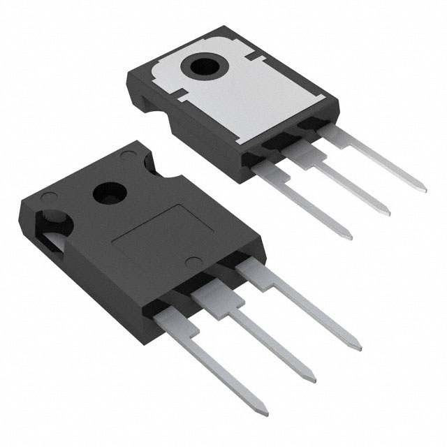
| Package / Case | TO-247-3 |
| Power - Max [Max] | 200 W |
| Reverse Recovery Time (trr) | 40 ns |
| Supplier Device Package | TO-247-3 |
| Switching Energy | 181 µJ, 305 µJ |
| Td (on/off) @ 25°C | 118 ns |
| Td (on/off) @ 25°C | 29.5 ns |
| Test Condition | 20 A, 15 V, 10 Ohm, 390 V |
| Vce(on) (Max) @ Vge, Ic | 2.5 V |
| Voltage - Collector Emitter Breakdown (Max) [Max] | 600 V |
Pricing
Prices provided here are for design reference only. For realtime values and availability, please visit the distributors directly
Description
General part information
STGW30M65DF2 Series
These devices are IGBTs developed using an advanced proprietary trench gate field-stop structure. The devices are part of the M series IGBTs, which represent an optimal balance between inverter system performance and efficiency where the low-loss and the short-circuit functionality are essential. Furthermore, the positive VCE(sat) temperature coefficient and the tight parameter distribution result in safer paralleling operation.
Documents
Technical documentation and resources