TPS621361RGXR
Active3-17V 4.0A STEP-DOWN CONVERTER WITH 1% ACCURACY AND PFM/FORCED-PWM IN 2X3QFN
TPS621361RGXR
Active3-17V 4.0A STEP-DOWN CONVERTER WITH 1% ACCURACY AND PFM/FORCED-PWM IN 2X3QFN
Description
General part information
TPS62136 Series
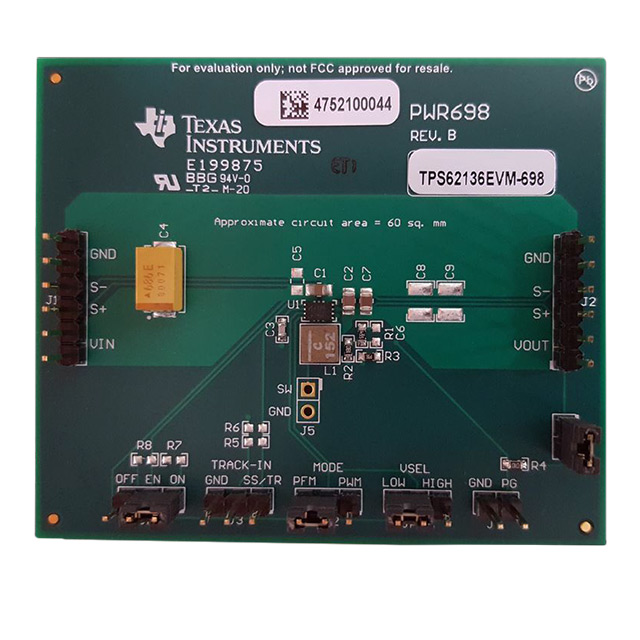
The TPS62136 and TPS621361 are high efficiency and easy to use synchronous step-down DC-DC converters, based on the DCS-Control™ Topology. The devices wide input voltage range of 3-V to 17-V makes it suitable for multi-cell Li-Ion as well as 12-V intermediate supply rails. The devices provide 4-A continuous output current. The TPS62136 automatically enters Power Save Mode at light loads to maintain high efficiency across the whole load range. With that, the device is well suited for applications that require connected standby performance, like ultra low power computers. With the MODE pin set to low, the switching frequency of the device is adapted automatically based on the input and output voltage. This technique is called Automatic Efficiency Enhancement (AEE™) and maintains high conversion efficiency over the whole operation range. It provides a 1% output voltage accuracy in PWM mode and therefore enables the design of a power supply with high output voltage accuracy.
The device has a typical quiescent current of 18 µA. In shutdown mode the current is typically 1 µA and the output is actively discharged for TPS62136 while the output voltage discharge feature is disabled in TPS621361.
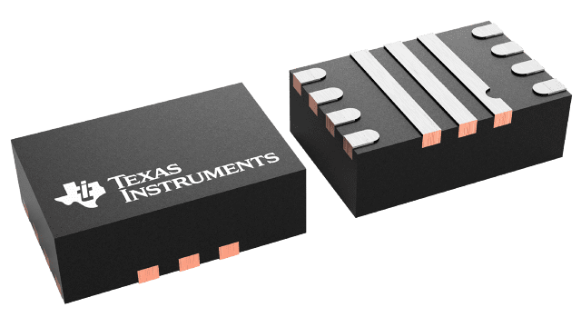
The TPS62136 is available as an adjustable version, packaged in a 3-mm x 2-mm VQFN package.
Technical Specifications
Parameters and characteristics for this part
| Specification | TPS621361RGXR |
|---|---|
| Current - Output | 4 A |
| Frequency - Switching | 1 MHz |
| Function | Step-Down |
| Mounting Type | Surface Mount |
| Number of Outputs | 1 |
| Operating Temperature (Max) | 125 °C |
| Operating Temperature (Min) | -40 °C |
| Output Configuration | Positive |
| Output Type | Adjustable |
| Package / Case | 11-VFQFN |
| Package Length | 2 mm |
| Package Name | 11-VQFN-HR |
| Package Width | 3 mm |
| Synchronous Rectifier | Yes |
| Topology | Buck |
| Voltage - Input (Max) | 17 V |
| Voltage - Input (Min) | 3 V |
| Voltage - Output (Max) | 12 V |
| Voltage - Output (Min/Fixed) | 0.8 V |
Pricing
Prices provided here are for design reference only. For realtime values and availability, please visit the distributors directly
Sign in to see pricing
Create a free account to access distributor pricing data.
CAD
3D models and CAD resources for this part
Documents
Technical documentation and resources