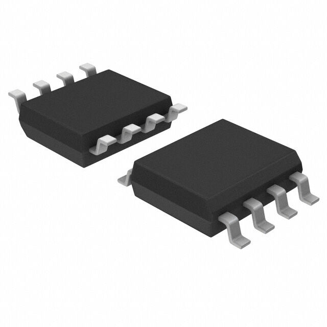
IR21531STRPBF
ActiveTHE IR21531S IS A HALF BRIDGE DRIVER, LO IN PHASE WITH RT, PROGRAMMABLE OSCILLATING FREQUENCY, 0.6ΜS DEADTIME (8-LEAD SOIC PACKAGE)
Deep-Dive with AI
Search across all available documentation for this part.

IR21531STRPBF
ActiveTHE IR21531S IS A HALF BRIDGE DRIVER, LO IN PHASE WITH RT, PROGRAMMABLE OSCILLATING FREQUENCY, 0.6ΜS DEADTIME (8-LEAD SOIC PACKAGE)
Deep-Dive with AI
Technical Specifications
Parameters and characteristics for this part
| Specification | IR21531STRPBF |
|---|---|
| Channel Type | Synchronous |
| Driven Configuration | Half-Bridge |
| Gate Type | N-Channel MOSFET |
| High Side Voltage - Max (Bootstrap) [Max] | 600 V |
| Input Type | RC Input Circuit |
| Mounting Type | Surface Mount |
| Number of Drivers | 2 |
| Operating Temperature [Max] | 125 ¯C |
| Operating Temperature [Min] | -40 °C |
| Package / Case | 8-SOIC |
| Package / Case [x] | 0.154 in |
| Package / Case [y] | 3.9 mm |
| Rise / Fall Time (Typ) [custom] | 45 ns |
| Rise / Fall Time (Typ) [custom] | 80 ns |
| Supplier Device Package | 8-SOIC |
| Voltage - Supply [Max] | 15.6 V |
| Voltage - Supply [Min] | 10 VDC |
Pricing
Prices provided here are for design reference only. For realtime values and availability, please visit the distributors directly
| Distributor | Package | Quantity | $ | |
|---|---|---|---|---|
| Digikey | Cut Tape (CT) | 1 | $ 2.86 | |
| 10 | $ 1.85 | |||
| 25 | $ 1.59 | |||
| 100 | $ 1.29 | |||
| 250 | $ 1.15 | |||
| 500 | $ 1.06 | |||
| 1000 | $ 0.99 | |||
| Digi-Reel® | 1 | $ 2.86 | ||
| 10 | $ 1.85 | |||
| 25 | $ 1.59 | |||
| 100 | $ 1.29 | |||
| 250 | $ 1.15 | |||
| 500 | $ 1.06 | |||
| 1000 | $ 0.99 | |||
| Tape & Reel (TR) | 2500 | $ 0.91 | ||
| 5000 | $ 0.86 | |||
| 7500 | $ 0.84 | |||
Description
General part information
IR21531 Series
IR21531STRPBF is a self-oscillating half-bridge gate driver. It incorporates a high-voltage half-bridge gate driver with a front-end oscillator similar to the industry standard CMOS 555 timer. The IR21531 provides more functionality and is easier to use than the previous IC. A shutdown feature has been designed into the CT pin so that both gate driver outputs can be disabled using a low-voltage control signal. In addition, the gate driver output pulse width is the same once the rising undervoltage lockout threshold on VCC has been reached, resulting in a more stable profile of frequency vs time at startup. Noise immunity has been improved significantly, both by lowering the peak di/dt of the gate driver, and by increasing the undervoltage lockout hysteresis to 1V. Finally, special attention has been paid to maximizing the latch immunity of the device, and providing comprehensive ESD protection on all pins.
Documents
Technical documentation and resources


