


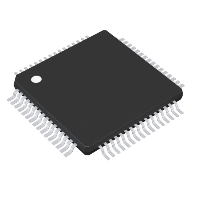
SN74ABTH182652APM
ActiveSCAN TEST DEVICES WITH 18-BIT TRANSCEIVERS AND REGISTERS

SN74ABTH182652APM
ActiveSCAN TEST DEVICES WITH 18-BIT TRANSCEIVERS AND REGISTERS
Description
General part information
SN74ABTH182652A Series
The 'ABTH18652A and 'ABTH182652A scan test devices with 18-bit bus transceivers and registers are members of the Texas Instruments SCOPETMtestability integrated-circuit family. This family of devices supports IEEE Standard 1149.1-1990 boundary scan to facilitate testing of complex circuit-board assemblies. Scan access to the test circuitry is accomplished via the 4-wire test access port (TAP) interface.
In the normal mode, these devices are 18-bit bus transceivers and registers that allow for multiplexed transmission of data directly from the input bus or from the internal registers. They can be used either as two 9-bit transceivers or one 18-bit transceiver. The test circuitry can be activated by the TAP to take snapshot samples of the data appearing at the device pins or to perform a self test on the boundary-test cells. Activating the TAP in the normal mode does not affect the functional operation of the SCOPETMbus transceivers and registers.
Data flow in each direction is controlled by clock (CLKAB and CLKBA), select (SAB and SBA), and output-enable (OEAB and) inputs. For A-to-B data flow, data on the A bus is clocked into the associated registers on the low-to-high transition of CLKAB. When SAB is low, real-time A data is selected for presentation to the B bus (transparent mode). When SAB is high, stored A data is selected for presentation to the B bus (registered mode). When OEAB is high, the B outputs are active. When OEAB is low, the B outputs are in the high-impedance state. Control for B-to-A data flow is similar to that for A-to-B data flow, but uses CLKBA, SBA, andinputs. Since theinput is active-low, the A outputs are active whenis low and are in the high-impedance state whenis high. Figure 1 illustrates the four fundamental bus-management functions that are performed with the 'ABTH18652A and 'ABTH182652A.
Technical Specifications
Parameters and characteristics for this part
| Specification | SN74ABTH182652APM |
|---|---|
| Logic Type | Scan Test Device, Transceivers, Registers |
| Mounting Type | Surface Mount |
| Number of Bits | 18 bits |
| Operating Temperature (Max) | 85 °C |
| Operating Temperature (Min) | -40 °C |
| Package / Case | 64-LQFP |
| Package Length | 10 mm |
| Package Name | 64-LQFP |
| Package Width | 10 mm |
| Supply Voltage (Max) | 5.5 V |
| Supply Voltage (Min) | 4.5 V |
Pricing
Prices provided here are for design reference only. For realtime values and availability, please visit the distributors directly
Sign in to see pricing
Create a free account to access distributor pricing data.
CAD
3D models and CAD resources for this part
Documents
Technical documentation and resources