SN65C3223DBR
Active3- TO 5.5-V DUAL CHANNEL 1MBPS RS-232 LINE DRIVER/RECEIVER WITH +/-15-KV ESD PROTECTION
SN65C3223DBR
Active3- TO 5.5-V DUAL CHANNEL 1MBPS RS-232 LINE DRIVER/RECEIVER WITH +/-15-KV ESD PROTECTION
Description
General part information
65C3223 Series
The SN65C3223 and SN75C3223 consist of two line drivers, two line receivers, and a dual charge-pump circuit with ±15-kV ESD protection pin to pin (serial-port connection pins, including GND). The devices provide the electrical interface between an asynchronous communication controller and the serial-port connector. The charge pump and four small external capacitors allow operation from a single 3-V to 5.5-V supply. The devices operate at data signaling rates up to 1 Mbit/s and a driver output slew rate of 24 V/µs to 150 V/µs.
Flexible control options for power management are available when the serial port is inactive. The auto-powerdown feature functions when FORCEON is low and FORCEOFF\ is high. During this mode of operation, if the device does not sense a valid RS-232 signal, the driver outputs are disabled. If FORCEOFF\ is set low and EN is high, both drivers and receivers are shut off, and the supply current is reduced to 1 µA. Disconnecting the serial port or turning off the peripheral drivers causes auto-powerdown to occur. Auto-powerdown can be disabled when FORCEON and FORCEOFF\ are high. With auto-powerdown enabled, the device is activated automatically when a valid signal is applied to any receiver input. The INVALID\ output is used to notify the user if an RS-232 signal is present at any receiver input. INVALID\ is high (valid data) if any receiver input voltage is greater than 2.7 V or less than –2.7 V or has been between –0.3 V and 0.3 V for less than 30 µs. INVALID\ is low (invalid data) if the receiver input voltage is between –0.3 V and 0.3 V for more than 30 µs. Refer to Figure 4 for receiver input levels.
The SN65C3223 and SN75C3223 consist of two line drivers, two line receivers, and a dual charge-pump circuit with ±15-kV ESD protection pin to pin (serial-port connection pins, including GND). The devices provide the electrical interface between an asynchronous communication controller and the serial-port connector. The charge pump and four small external capacitors allow operation from a single 3-V to 5.5-V supply. The devices operate at data signaling rates up to 1 Mbit/s and a driver output slew rate of 24 V/µs to 150 V/µs.
Technical Specifications
Parameters and characteristics for this part
| Specification | SN65C3223DBR |
|---|---|
| Data Rate | 1 Mbps |
| Duplex | Full |
| Mounting Type | Surface Mount |
| Number of Drivers | 2 |
| Number of Receivers | 2 |
| Operating Temperature (Max) | 85 °C |
| Operating Temperature (Min) | -40 °C |
| Package Length | 0.209 in |
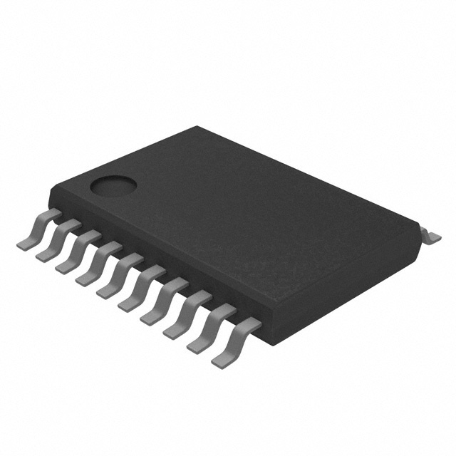
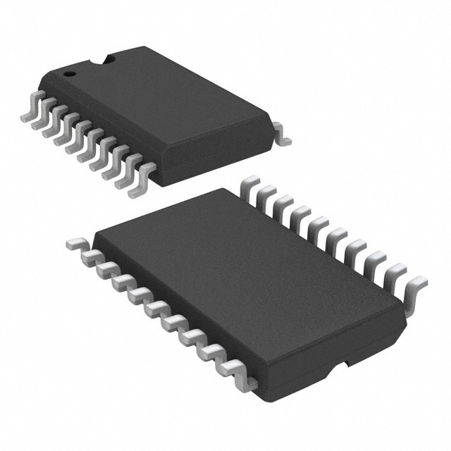
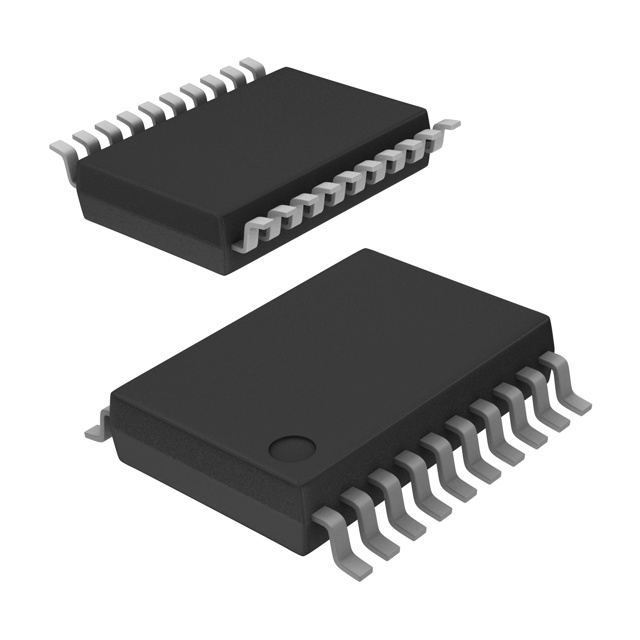
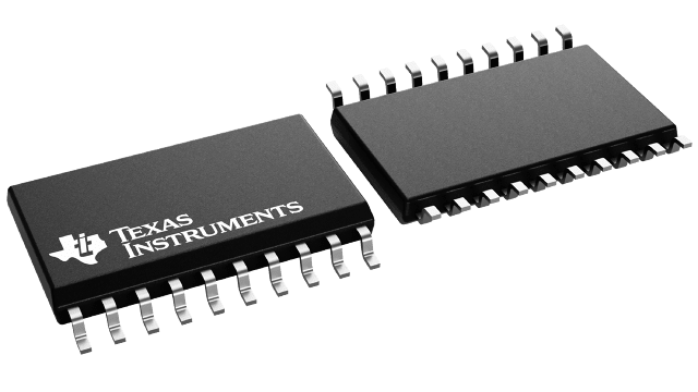
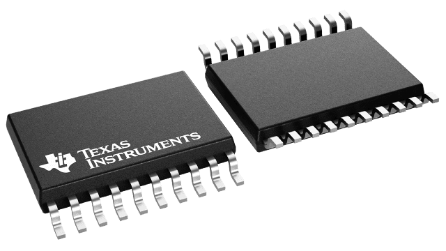
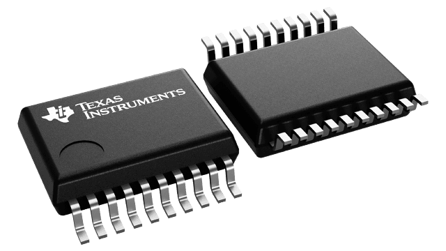
| Package Name | 20-SSOP |
| Package Width | 5.3 mm |
| Protocol | RS232 |
| Receiver Hysteresis | 500 mV |
| Type | Transceiver |
| Voltage - Supply (Maximum) | 5.5 V |
| Voltage - Supply (Minimum) | 3 V |
Pricing
Prices provided here are for design reference only. For realtime values and availability, please visit the distributors directly
Sign in to see pricing
Create a free account to access distributor pricing data.
CAD
3D models and CAD resources for this part
Documents
Technical documentation and resources