CD4021BNSR
ObsoleteIC STATIC SHFT REG 8STG 16SO
CD4021BNSR
ObsoleteIC STATIC SHFT REG 8STG 16SO
Description
General part information
CD4021 Series
CD4021B series types are 8-stage parallel- or serial-input/serial output registers having common CLOCK and PARALLEL/SERIAL CONTROL inputs, a single SERIAL data input, and individual parallel "JAM" inputs to each register stage. Each register stage is a D-type, master-slave flip-flop. In addition to an output from stage 8, "Q" outputs are also available from stages 6 and 7. Parallel as well as serial entry is made into the register synchronously with the positive clock line transition in the CD4014B. In the CD4021B serial entry is synchronous with the clock but parallel entry is asynchronous. In both types, entry is controlled by the PARALLEL/SERIAL CONTROL input. When the PARALLEL/SERIAL CONTROL input is low, data is serially shifted into the 8-stage register synchronously with the positive transition of the clock line. When the PARALLEL/SERIAL CONTROL input is high, data is jammed into the 8-stage register via the parallel input lines and synchronous with the positive transition of the clock line. In the CD4021B, the CLOCK input of the internal stage is "forced" when asynchronous parallel entry is made. Register expansion using multiple packages is permitted.
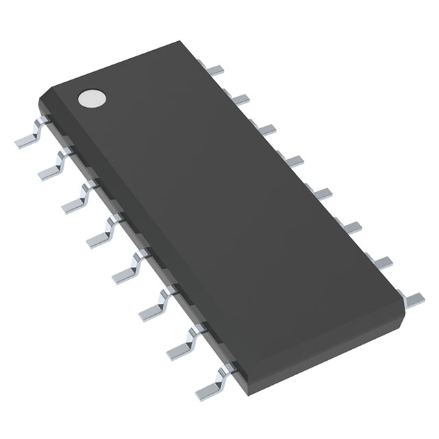
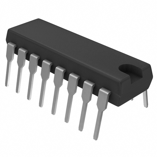
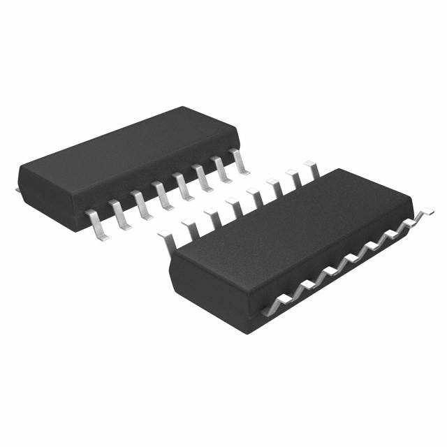
The CD4021B series types are supplied in 16-lead hermetic dual-in-line ceramic packages (D and F suffixes), 16-lead dual-in-line plastic packages (E suffix), and in chip form (H suffix).
CD4021B series types are 8-stage parallel- or serial-input/serial output registers having common CLOCK and PARALLEL/SERIAL CONTROL inputs, a single SERIAL data input, and individual parallel "JAM" inputs to each register stage. Each register stage is a D-type, master-slave flip-flop. In addition to an output from stage 8, "Q" outputs are also available from stages 6 and 7. Parallel as well as serial entry is made into the register synchronously with the positive clock line transition in the CD4014B. In the CD4021B serial entry is synchronous with the clock but parallel entry is asynchronous. In both types, entry is controlled by the PARALLEL/SERIAL CONTROL input. When the PARALLEL/SERIAL CONTROL input is low, data is serially shifted into the 8-stage register synchronously with the positive transition of the clock line. When the PARALLEL/SERIAL CONTROL input is high, data is jammed into the 8-stage register via the parallel input lines and synchronous with the positive transition of the clock line. In the CD4021B, the CLOCK input of the internal stage is "forced" when asynchronous parallel entry is made. Register expansion using multiple packages is permitted.
Technical Specifications
Parameters and characteristics for this part
| Specification | CD4021BNSR |
|---|---|
| Function | Parallel or Serial to Serial |
| Logic Type | Shift Register |
| Mounting Type | Surface Mount |
| Number of Bits per Element | 8 bits |
| Number of Elements | 1 |
| Operating Temperature (Max) | 125 °C |
| Operating Temperature (Min) | -55 °C |
| Output Type | Push-Pull |
| Package Length | 0.209 in |
| Package Name | 16-SO, 16-SOIC |
| Package Width | 5.3 mm |
| Voltage - Supply (Maximum) | 18 V |
| Voltage - Supply (Minimum) | 3 V |
Pricing
Prices provided here are for design reference only. For realtime values and availability, please visit the distributors directly
Sign in to see pricing
Create a free account to access distributor pricing data.
CAD
3D models and CAD resources for this part
Documents
Technical documentation and resources
No documents available