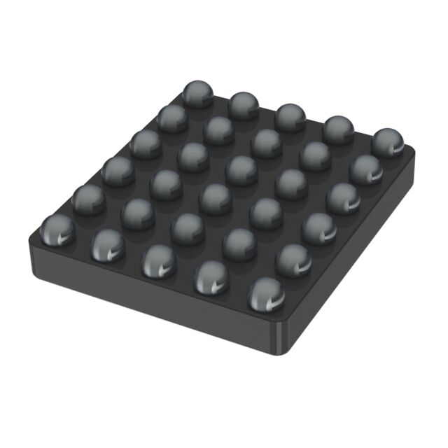
BQ25638YBGR
ActiveI²C CONTROLLED, 1-CELL 5-A MAXIMUM 18-V INPUT BUCK CHARGER WITH NVDC POWER PATH AND USB OTG OUTPUT
Deep-Dive with AI
Search across all available documentation for this part.

BQ25638YBGR
ActiveI²C CONTROLLED, 1-CELL 5-A MAXIMUM 18-V INPUT BUCK CHARGER WITH NVDC POWER PATH AND USB OTG OUTPUT
Deep-Dive with AI
Technical Specifications
Parameters and characteristics for this part
| Specification | BQ25638YBGR |
|---|---|
| Battery Chemistry | Lithium Ion/Polymer |
| Battery Pack Voltage | 9.6 V |
| Charge Current - Max [Max] | 5 A |
| Current - Charging | Constant - Programmable |
| Interface | I2C |
| Mounting Type | Surface Mount |
| Number of Cells | 1 |
| Operating Temperature [Max] | 85 °C |
| Operating Temperature [Min] | -40 °C |
| Package / Case | DSBGA, 30-XFBGA |
| Programmable Features | Current, Timer, Voltage |
| Supplier Device Package | 30-DSBGA |
| Supplier Device Package [x] | 1.98 |
| Supplier Device Package [y] | 2.27 |
| Voltage - Supply (Max) [Max] | 18 V |
Pricing
Prices provided here are for design reference only. For realtime values and availability, please visit the distributors directly
| Distributor | Package | Quantity | $ | |
|---|---|---|---|---|
| Digikey | Cut Tape (CT) | 1 | $ 3.56 | |
| 10 | $ 3.20 | |||
| 25 | $ 3.02 | |||
| 100 | $ 2.62 | |||
| 250 | $ 2.49 | |||
| 500 | $ 2.23 | |||
| 1000 | $ 1.88 | |||
| 2500 | $ 1.79 | |||
| Digi-Reel® | 1 | $ 3.56 | ||
| 10 | $ 3.20 | |||
| 25 | $ 3.02 | |||
| 100 | $ 2.62 | |||
| 250 | $ 2.49 | |||
| 500 | $ 2.23 | |||
| 1000 | $ 1.88 | |||
| 2500 | $ 1.79 | |||
| Tape & Reel (TR) | 6000 | $ 1.72 | ||
| Texas Instruments | LARGE T&R | 1 | $ 2.69 | |
| 100 | $ 2.35 | |||
| 250 | $ 1.65 | |||
| 1000 | $ 1.33 | |||
BQ25638 Series
I²C controlled, 1-cell 5-A maximum 18-V input buck charger with NVDC power path and USB OTG output
| Part | Supplier Device Package [y] | Supplier Device Package | Supplier Device Package [x] | Programmable Features | Current - Charging | Battery Pack Voltage | Battery Chemistry | Mounting Type | Package / Case | Operating Temperature [Min] | Operating Temperature [Max] | Charge Current - Max [Max] | Number of Cells | Voltage - Supply (Max) [Max] | Interface |
|---|---|---|---|---|---|---|---|---|---|---|---|---|---|---|---|
Texas Instruments BQ25638YBGR | 2.27 | 30-DSBGA | 1.98 | Current, Timer, Voltage | Constant - Programmable | 9.6 V | Lithium Ion/Polymer | Surface Mount | 30-XFBGA, DSBGA | -40 °C | 85 °C | 5 A | 1 | 18 V | I2C |
Description
General part information
BQ25638 Series
The BQ25638 is a highly-integrated 5-A switch-mode battery charge management and system power path management device for single cell Li-Ion and Li-polymer batteries. The solution is highly integrated with built-in current sensing, loop compensation, input reverse-blocking FET (RBFET, Q1), high-side switching FET (HSFET, Q2), low-side switching FET (LSFET, Q3), and battery FET (BATFET, Q4) between system and battery. It uses NVDC power path management, regulating the system slightly above the battery voltage without dropping below a configurable minimum system voltage. The low impedance power path optimizes switch-mode operation efficiency, reduces battery charging time and extends battery life during discharging phase. The I 2C serial interface with charging and system settings makes BQ25638 a truly flexible solution.
The device supports a wide range of input sources, including standard USB host port, USB charging port, and USB compliant high voltage adapter. It is compliant with USB 2.0 and USB 3.0 power specifications for input current and voltage regulation. In addition, the Input Current Optimizer (ICO) supports the detection of maximum power point of the input source without overload. BQ25638 has an ILIM pin to set the default input current limit and a TS_BIAS pin for controlled thermistor bias. The device also meets USB On-the-Go (OTG) operation power rating specification with constant current limit up to 3.2 A.
The power path management regulates the system slightly above battery voltage but does not drop below the programmable minimum system voltage. With this feature, the system maintains operation even when the battery is completely depleted or removed. When the input current limit or input voltage limit is reached, the power path management automatically reduces the charge current. If the system load continues to increase, the power path discharges the battery until the system power requirement is met. This supplement mode prevents overloading the input source.
Documents
Technical documentation and resources


