CD74HCT74M96G4
ActiveHIGH SPEED CMOS LOGIC DUAL POSITIVE-EDGE-TRIGGERED D FLIP-FLOPS WITH SET AND RESET
Deep-Dive with AI
Search across all available documentation for this part.
CD74HCT74M96G4
ActiveHIGH SPEED CMOS LOGIC DUAL POSITIVE-EDGE-TRIGGERED D FLIP-FLOPS WITH SET AND RESET
Deep-Dive with AI
Technical Specifications
Parameters and characteristics commom to parts in this series
| Specification | CD74HCT74M96G4 | 74HCT74 Series |
|---|---|---|
| Clock Frequency | 50 MHz | 46 - 50 MHz |
| Current - Output High, Low | 4 mA, 4 mA | 4 mA |
| Current - Quiescent (Iq) | 4 çA | 4 çA |
| Function | Reset, Set(Preset) | Reset, Set(Preset) |
| Input Capacitance | 10 pF | 3 - 10 pF |
| Max Propagation Delay @ V, Max CL | 35 ns | 18 - 35 ns |
| Mounting Type | Surface Mount | Surface Mount, Through Hole |
| Number of Bits per Element | 1 | 1 |
| Number of Elements [custom] | 2 | 2 |
| Operating Temperature [Max] | 125 °C | 85 - 125 °C |
| Operating Temperature [Min] | -55 C | -55 - -40 °C |
| Output Type | Complementary | Complementary |
| Package / Case | 3.9 mm | 3.9 - 7.62 mm |
| Package / Case | 0.154 in | 0.154 - 5.3 in |
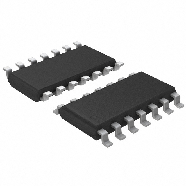
| Package / Case | 14-SOIC | 14-SOIC, 14-SSOP, 14-DIP, 14-TSSOP |
| Package / Case | - | 0.209 in |
| Package / Case | - | 0.173 in |
| Package / Case | - | 4.4 mm |
| Package / Case | - | 5.3 mm |
| Package / Case | - | 0.209 in |
| Supplier Device Package | - | 14-SSOP, 14-TSSOP, 14-SO |
| Trigger Type | Positive Edge | Positive Edge |
| Type | D-Type | D-Type |
| Voltage - Supply [Max] | 5.5 V | 5.5 V |
| Voltage - Supply [Min] | 4.5 V | 4.5 V |
Pricing
Prices provided here are for design reference only. For realtime values and availability, please visit the distributors directly
74HCT74 Series
IC FF D-TYPE DUAL 1BIT 14SOIC
| Part | Input Capacitance | Current - Quiescent (Iq) | Function | Mounting Type | Number of Elements [custom] | Voltage - Supply [Max] | Voltage - Supply [Min] | Current - Output High, Low | Trigger Type | Max Propagation Delay @ V, Max CL | Package / Case | Package / Case | Package / Case | Output Type | Number of Bits per Element | Operating Temperature [Max] | Operating Temperature [Min] | Clock Frequency | Type | Package / Case | Supplier Device Package | Package / Case [custom] | Package / Case [custom] | Package / Case [y] | Package / Case [y] |
|---|---|---|---|---|---|---|---|---|---|---|---|---|---|---|---|---|---|---|---|---|---|---|---|---|---|
Texas Instruments SN74HCT74DG4Flip Flop 2 Element D-Type 1 Bit Positive Edge 14-SOIC (0.154", 3.90mm Width) | 3 pF | 4 çA | Reset, Set(Preset) | Surface Mount | 2 | 5.5 V | 4.5 V | 4 mA, 4 mA | Positive Edge | 25 ns | 3.9 mm | 0.154 in | 14-SOIC | Complementary | 1 | 85 °C | -40 °C | 46 MHz | D-Type | ||||||
Texas Instruments CD74HCT74ME4Flip Flop 2 Element D-Type 1 Bit Positive Edge 14-SOIC (0.154", 3.90mm Width) | 10 pF | 4 çA | Reset, Set(Preset) | Surface Mount | 2 | 5.5 V | 4.5 V | 4 mA, 4 mA | Positive Edge | 35 ns | 3.9 mm | 0.154 in | 14-SOIC | Complementary | 1 | 125 °C | -55 C | 50 MHz | D-Type | ||||||
Texas Instruments SN74HCT74DE4Flip Flop 2 Element D-Type 1 Bit Positive Edge 14-SOIC (0.154", 3.90mm Width) | 3 pF | 4 çA | Reset, Set(Preset) | Surface Mount | 2 | 5.5 V | 4.5 V | 4 mA, 4 mA | Positive Edge | 25 ns | 3.9 mm | 0.154 in | 14-SOIC | Complementary | 1 | 85 °C | -40 °C | 46 MHz | D-Type | ||||||
Texas Instruments SN74HCT74DBRThe ’HCT74 devices contain two independent D-type positive-edge-triggered flip-flops. A low level at the preset ( PRE) or clear ( CLR) inputs sets or resets the outputs, regardless of the levels of the other inputs. When PRE and CLR are inactive (high), data at the data (D) input meeting the setup time requirements are transferred to the outputs on the positive-going edge of the clock (CLK) pulse. Clock triggering occurs at a voltage level and is not directly related to the rise time of CLK. Following the hold-time interval, data at the D input may be changed without affecting the levels at the outputs.
The ’HCT74 devices contain two independent D-type positive-edge-triggered flip-flops. A low level at the preset ( PRE) or clear ( CLR) inputs sets or resets the outputs, regardless of the levels of the other inputs. When PRE and CLR are inactive (high), data at the data (D) input meeting the setup time requirements are transferred to the outputs on the positive-going edge of the clock (CLK) pulse. Clock triggering occurs at a voltage level and is not directly related to the rise time of CLK. Following the hold-time interval, data at the D input may be changed without affecting the levels at the outputs. | 3 pF | 4 çA | Reset, Set(Preset) | Surface Mount | 2 | 5.5 V | 4.5 V | 4 mA, 4 mA | Positive Edge | 25 ns | 5.3 mm | 14-SSOP | Complementary | 1 | 85 °C | -40 °C | 46 MHz | D-Type | 0.209 in | 14-SSOP | |||||
Texas Instruments CD74HCT74M96The CDx4HCT74-Q1 devices contain two independent D-type positive-edge-triggered flip-flops with asynchronous preset and clear pins for each.
The CDx4HCT74-Q1 devices contain two independent D-type positive-edge-triggered flip-flops with asynchronous preset and clear pins for each. | 10 pF | 4 çA | Reset, Set(Preset) | Surface Mount | 2 | 5.5 V | 4.5 V | 4 mA, 4 mA | Positive Edge | 35 ns | 3.9 mm | 0.154 in | 14-SOIC | Complementary | 1 | 125 °C | -55 C | 50 MHz | D-Type | ||||||
3 pF | 4 çA | Reset, Set(Preset) | Through Hole | 2 | 5.5 V | 4.5 V | 4 mA, 4 mA | Positive Edge | 25 ns | 7.62 mm | 0.3 in | 14-DIP | Complementary | 1 | 85 °C | -40 °C | 46 MHz | D-Type | |||||||
Texas Instruments SN74HCT74DRE4The ’HCT74 devices contain two independent D-type positive-edge-triggered flip-flops. A low level at the preset ( PRE) or clear ( CLR) inputs sets or resets the outputs, regardless of the levels of the other inputs. When PRE and CLR are inactive (high), data at the data (D) input meeting the setup time requirements are transferred to the outputs on the positive-going edge of the clock (CLK) pulse. Clock triggering occurs at a voltage level and is not directly related to the rise time of CLK. Following the hold-time interval, data at the D input may be changed without affecting the levels at the outputs.
The ’HCT74 devices contain two independent D-type positive-edge-triggered flip-flops. A low level at the preset ( PRE) or clear ( CLR) inputs sets or resets the outputs, regardless of the levels of the other inputs. When PRE and CLR are inactive (high), data at the data (D) input meeting the setup time requirements are transferred to the outputs on the positive-going edge of the clock (CLK) pulse. Clock triggering occurs at a voltage level and is not directly related to the rise time of CLK. Following the hold-time interval, data at the D input may be changed without affecting the levels at the outputs. | 3 pF | 4 çA | Reset, Set(Preset) | Surface Mount | 2 | 5.5 V | 4.5 V | 4 mA, 4 mA | Positive Edge | 25 ns | 3.9 mm | 0.154 in | 14-SOIC | Complementary | 1 | 85 °C | -40 °C | 46 MHz | D-Type | ||||||
Texas Instruments SN74HCT74PWTFlip Flop 2 Element D-Type 1 Bit Positive Edge 14-TSSOP (0.173", 4.40mm Width) | 3 pF | 4 çA | Reset, Set(Preset) | Surface Mount | 2 | 5.5 V | 4.5 V | 4 mA, 4 mA | Positive Edge | 25 ns | 14-TSSOP | Complementary | 1 | 85 °C | -40 °C | 46 MHz | D-Type | 14-TSSOP | 0.173 in | 4.4 mm | |||||
Texas Instruments SN74HCT74DRG4Flip Flop 2 Element D-Type 1 Bit Positive Edge 14-SOIC (0.154", 3.90mm Width) | 3 pF | 4 çA | Reset, Set(Preset) | Surface Mount | 2 | 5.5 V | 4.5 V | 4 mA, 4 mA | Positive Edge | 25 ns | 3.9 mm | 0.154 in | 14-SOIC | Complementary | 1 | 85 °C | -40 °C | 46 MHz | D-Type | ||||||
Texas Instruments SN74HCT74NSRThe ’HCT74 devices contain two independent D-type positive-edge-triggered flip-flops. A low level at the preset ( PRE) or clear ( CLR) inputs sets or resets the outputs, regardless of the levels of the other inputs. When PRE and CLR are inactive (high), data at the data (D) input meeting the setup time requirements are transferred to the outputs on the positive-going edge of the clock (CLK) pulse. Clock triggering occurs at a voltage level and is not directly related to the rise time of CLK. Following the hold-time interval, data at the D input may be changed without affecting the levels at the outputs.
The ’HCT74 devices contain two independent D-type positive-edge-triggered flip-flops. A low level at the preset ( PRE) or clear ( CLR) inputs sets or resets the outputs, regardless of the levels of the other inputs. When PRE and CLR are inactive (high), data at the data (D) input meeting the setup time requirements are transferred to the outputs on the positive-going edge of the clock (CLK) pulse. Clock triggering occurs at a voltage level and is not directly related to the rise time of CLK. Following the hold-time interval, data at the D input may be changed without affecting the levels at the outputs. | 3 pF | 4 çA | Reset, Set(Preset) | Surface Mount | 2 | 5.5 V | 4.5 V | 4 mA, 4 mA | Positive Edge | 25 ns | 14-SOIC | Complementary | 1 | 85 °C | -40 °C | 46 MHz | D-Type | 14-SO | 5.3 mm | 0.209 in | |||||
Texas Instruments SN74HCT74NSFlip Flop 2 Element D-Type 1 Bit Positive Edge 14-SOIC (0.209", 5.30mm Width) | 3 pF | 4 çA | Reset, Set(Preset) | Surface Mount | 2 | 5.5 V | 4.5 V | 4 mA, 4 mA | Positive Edge | 25 ns | 14-SOIC | Complementary | 1 | 85 °C | -40 °C | 46 MHz | D-Type | 14-SO | 5.3 mm | 0.209 in | |||||
Texas Instruments SN74HCT74DRThe ’HCT74 devices contain two independent D-type positive-edge-triggered flip-flops. A low level at the preset ( PRE) or clear ( CLR) inputs sets or resets the outputs, regardless of the levels of the other inputs. When PRE and CLR are inactive (high), data at the data (D) input meeting the setup time requirements are transferred to the outputs on the positive-going edge of the clock (CLK) pulse. Clock triggering occurs at a voltage level and is not directly related to the rise time of CLK. Following the hold-time interval, data at the D input may be changed without affecting the levels at the outputs.
The ’HCT74 devices contain two independent D-type positive-edge-triggered flip-flops. A low level at the preset ( PRE) or clear ( CLR) inputs sets or resets the outputs, regardless of the levels of the other inputs. When PRE and CLR are inactive (high), data at the data (D) input meeting the setup time requirements are transferred to the outputs on the positive-going edge of the clock (CLK) pulse. Clock triggering occurs at a voltage level and is not directly related to the rise time of CLK. Following the hold-time interval, data at the D input may be changed without affecting the levels at the outputs. | 3 pF | 4 çA | Reset, Set(Preset) | Surface Mount | 2 | 5.5 V | 4.5 V | 4 mA, 4 mA | Positive Edge | 18 ns | 3.9 mm | 0.154 in | 14-SOIC | Complementary | 1 | 85 °C | -40 °C | 46 MHz | D-Type | ||||||
Texas Instruments SN74HCT74PWThe ’HCT74 devices contain two independent D-type positive-edge-triggered flip-flops. A low level at the preset ( PRE) or clear ( CLR) inputs sets or resets the outputs, regardless of the levels of the other inputs. When PRE and CLR are inactive (high), data at the data (D) input meeting the setup time requirements are transferred to the outputs on the positive-going edge of the clock (CLK) pulse. Clock triggering occurs at a voltage level and is not directly related to the rise time of CLK. Following the hold-time interval, data at the D input may be changed without affecting the levels at the outputs.
The ’HCT74 devices contain two independent D-type positive-edge-triggered flip-flops. A low level at the preset ( PRE) or clear ( CLR) inputs sets or resets the outputs, regardless of the levels of the other inputs. When PRE and CLR are inactive (high), data at the data (D) input meeting the setup time requirements are transferred to the outputs on the positive-going edge of the clock (CLK) pulse. Clock triggering occurs at a voltage level and is not directly related to the rise time of CLK. Following the hold-time interval, data at the D input may be changed without affecting the levels at the outputs. | 3 pF | 4 çA | Reset, Set(Preset) | Surface Mount | 2 | 5.5 V | 4.5 V | 4 mA, 4 mA | Positive Edge | 25 ns | 14-TSSOP | Complementary | 1 | 85 °C | -40 °C | 46 MHz | D-Type | 14-TSSOP | 0.173 in | 4.4 mm | |||||
Texas Instruments CD74HCT74EThe CDx4HCT74-Q1 devices contain two independent D-type positive-edge-triggered flip-flops with asynchronous preset and clear pins for each.
The CDx4HCT74-Q1 devices contain two independent D-type positive-edge-triggered flip-flops with asynchronous preset and clear pins for each. | 10 pF | 4 çA | Reset, Set(Preset) | Through Hole | 2 | 5.5 V | 4.5 V | 4 mA, 4 mA | Positive Edge | 35 ns | 7.62 mm | 0.3 in | 14-DIP | Complementary | 1 | 125 °C | -55 C | 50 MHz | D-Type | ||||||
Texas Instruments CD74HCT74M96G4The CDx4HCT74-Q1 devices contain two independent D-type positive-edge-triggered flip-flops with asynchronous preset and clear pins for each.
The CDx4HCT74-Q1 devices contain two independent D-type positive-edge-triggered flip-flops with asynchronous preset and clear pins for each. | 10 pF | 4 çA | Reset, Set(Preset) | Surface Mount | 2 | 5.5 V | 4.5 V | 4 mA, 4 mA | Positive Edge | 35 ns | 3.9 mm | 0.154 in | 14-SOIC | Complementary | 1 | 125 °C | -55 C | 50 MHz | D-Type | ||||||
Texas Instruments SN74HCT74ADBRFlip Flop 2 Element D-Type 1 Bit Positive Edge 14-SSOP (0.209", 5.30mm Width) | 3 pF | 4 çA | Reset, Set(Preset) | Surface Mount | 2 | 5.5 V | 4.5 V | 4 mA, 4 mA | Positive Edge | 25 ns | 5.3 mm | 14-SSOP | Complementary | 1 | 85 °C | -40 °C | 46 MHz | D-Type | 0.209 in | 14-SSOP | |||||
Texas Instruments SN74HCT74NSRE4Flip Flop 2 Element D-Type 1 Bit Positive Edge 14-SOIC (0.209", 5.30mm Width) | 3 pF | 4 çA | Reset, Set(Preset) | Surface Mount | 2 | 5.5 V | 4.5 V | 4 mA, 4 mA | Positive Edge | 25 ns | 14-SOIC | Complementary | 1 | 85 °C | -40 °C | 46 MHz | D-Type | 14-SO | 5.3 mm | 0.209 in | |||||
Texas Instruments SN74HCT74NThe ’HCT74 devices contain two independent D-type positive-edge-triggered flip-flops. A low level at the preset ( PRE) or clear ( CLR) inputs sets or resets the outputs, regardless of the levels of the other inputs. When PRE and CLR are inactive (high), data at the data (D) input meeting the setup time requirements are transferred to the outputs on the positive-going edge of the clock (CLK) pulse. Clock triggering occurs at a voltage level and is not directly related to the rise time of CLK. Following the hold-time interval, data at the D input may be changed without affecting the levels at the outputs.
The ’HCT74 devices contain two independent D-type positive-edge-triggered flip-flops. A low level at the preset ( PRE) or clear ( CLR) inputs sets or resets the outputs, regardless of the levels of the other inputs. When PRE and CLR are inactive (high), data at the data (D) input meeting the setup time requirements are transferred to the outputs on the positive-going edge of the clock (CLK) pulse. Clock triggering occurs at a voltage level and is not directly related to the rise time of CLK. Following the hold-time interval, data at the D input may be changed without affecting the levels at the outputs. | 3 pF | 4 çA | Reset, Set(Preset) | Through Hole | 2 | 5.5 V | 4.5 V | 4 mA, 4 mA | Positive Edge | 25 ns | 7.62 mm | 0.3 in | 14-DIP | Complementary | 1 | 85 °C | -40 °C | 46 MHz | D-Type | ||||||
Texas Instruments SN74HCT74DTFlip Flop 2 Element D-Type 1 Bit Positive Edge 14-SOIC (0.154", 3.90mm Width) | 3 pF | 4 çA | Reset, Set(Preset) | Surface Mount | 2 | 5.5 V | 4.5 V | 4 mA, 4 mA | Positive Edge | 25 ns | 3.9 mm | 0.154 in | 14-SOIC | Complementary | 1 | 85 °C | -40 °C | 46 MHz | D-Type | ||||||
Texas Instruments SN74HCT74PWRThe ’HCT74 devices contain two independent D-type positive-edge-triggered flip-flops. A low level at the preset ( PRE) or clear ( CLR) inputs sets or resets the outputs, regardless of the levels of the other inputs. When PRE and CLR are inactive (high), data at the data (D) input meeting the setup time requirements are transferred to the outputs on the positive-going edge of the clock (CLK) pulse. Clock triggering occurs at a voltage level and is not directly related to the rise time of CLK. Following the hold-time interval, data at the D input may be changed without affecting the levels at the outputs.
The ’HCT74 devices contain two independent D-type positive-edge-triggered flip-flops. A low level at the preset ( PRE) or clear ( CLR) inputs sets or resets the outputs, regardless of the levels of the other inputs. When PRE and CLR are inactive (high), data at the data (D) input meeting the setup time requirements are transferred to the outputs on the positive-going edge of the clock (CLK) pulse. Clock triggering occurs at a voltage level and is not directly related to the rise time of CLK. Following the hold-time interval, data at the D input may be changed without affecting the levels at the outputs. | 3 pF | 4 çA | Reset, Set(Preset) | Surface Mount | 2 | 5.5 V | 4.5 V | 4 mA, 4 mA | Positive Edge | 25 ns | 14-TSSOP | Complementary | 1 | 85 °C | -40 °C | 46 MHz | D-Type | 14-TSSOP | 0.173 in | 4.4 mm | |||||
Texas Instruments CD74HCT74MTThe CDx4HCT74-Q1 devices contain two independent D-type positive-edge-triggered flip-flops with asynchronous preset and clear pins for each.
The CDx4HCT74-Q1 devices contain two independent D-type positive-edge-triggered flip-flops with asynchronous preset and clear pins for each. | 10 pF | 4 çA | Reset, Set(Preset) | Surface Mount | 2 | 5.5 V | 4.5 V | 4 mA, 4 mA | Positive Edge | 35 ns | 3.9 mm | 0.154 in | 14-SOIC | Complementary | 1 | 125 °C | -55 C | 50 MHz | D-Type | ||||||
Texas Instruments CD74HCT74MThe CDx4HCT74-Q1 devices contain two independent D-type positive-edge-triggered flip-flops with asynchronous preset and clear pins for each.
The CDx4HCT74-Q1 devices contain two independent D-type positive-edge-triggered flip-flops with asynchronous preset and clear pins for each. | 10 pF | 4 çA | Reset, Set(Preset) | Surface Mount | 2 | 5.5 V | 4.5 V | 4 mA, 4 mA | Positive Edge | 35 ns | 3.9 mm | 0.154 in | 14-SOIC | Complementary | 1 | 125 °C | -55 C | 50 MHz | D-Type | ||||||
Texas Instruments CD74HCT74MTE4Flip Flop 2 Element D-Type 1 Bit Positive Edge 14-SOIC (0.154", 3.90mm Width) | 10 pF | 4 çA | Reset, Set(Preset) | Surface Mount | 2 | 5.5 V | 4.5 V | 4 mA, 4 mA | Positive Edge | 35 ns | 3.9 mm | 0.154 in | 14-SOIC | Complementary | 1 | 125 °C | -55 C | 50 MHz | D-Type |
Description
General part information
74HCT74 Series
The CDx4HCT74-Q1 devices contain two independent D-type positive-edge-triggered flip-flops with asynchronous preset and clear pins for each.
The CDx4HCT74-Q1 devices contain two independent D-type positive-edge-triggered flip-flops with asynchronous preset and clear pins for each.
Documents
Technical documentation and resources