


SN74AVCH24T245 Series
24-bit dual-supply bus transceiver with configurable voltage translation and 3-state outputs
Manufacturer: Texas Instruments
Catalog
24-bit dual-supply bus transceiver with configurable voltage translation and 3-state outputs
Description
AI
This 24-bit noninverting bus transceiver uses two separate configurable power-supply rails. The SN74AVCH24T245 is optimized to operate with VCCA/VCCBset at 1.4 V to 3.6 V. It is operational with VCCA/VCCBas low as 1.2 V. The A port is designed to track VCCA. VCCAaccepts any supply voltage from 1.2 V to 3.6 V. The B port is designed to track VCCB. VCCBaccepts any supply voltage from 1.2 V to 3.6 V. This allows for universal low-voltage bidirectional translation between any of the 1.2-V, 1.5-V, 1.8-V, 2.5-V, and 3.3-V voltage nodes.
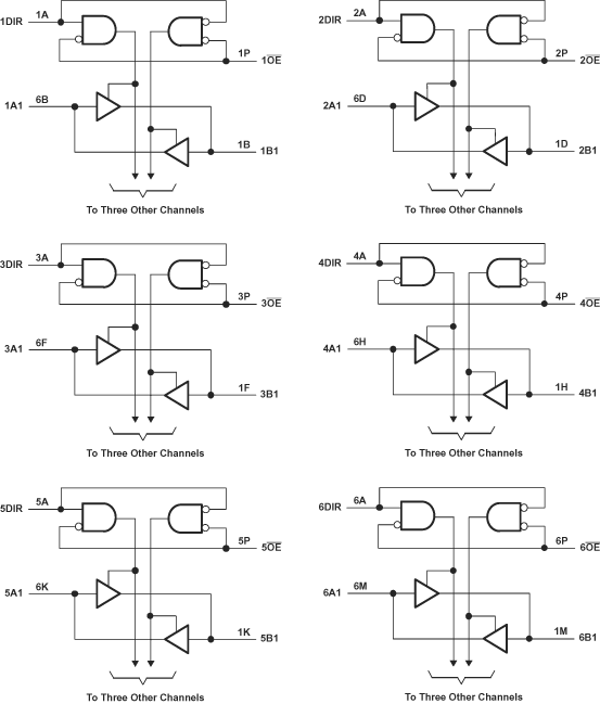
The SN74AVCH24T245 is designed for asynchronous communication between data buses. The device transmits data from the A bus to the B bus or from the B bus to the A bus, depending on the logic level at the direction-control (DIR) input. The output-enable (OE) input can be used to disable the outputs so the buses are effectively isolated.
The SN74AVCH24T245 is designed so that the control pins (1DIR, 2DIR, 3DIR, 4DIR, 5DIR, 6DIR, 1OE, 2OE, 3OE, 4OE, 5OE, and 6OE) are supplied by VCCA.
This device is fully specified for partial-power-down applications using Ioff. The Ioffcircuitry disables the outputs, preventing damaging current backflow through the device when it is powered down.
The VCCisolation feature ensures that if either VCCinput is at GND, then both ports are in the high-impedance state.
Active bus-hold circuitry holds unused or undriven inputs at a valid logic state.
To ensure the high-impedance state during power up or power down,OEshould be tied to VCCAthrough a pullup resistor; the minimum value of the resistor is determined by the current-sinking capability of the driver.
This 24-bit noninverting bus transceiver uses two separate configurable power-supply rails. The SN74AVCH24T245 is optimized to operate with VCCA/VCCBset at 1.4 V to 3.6 V. It is operational with VCCA/VCCBas low as 1.2 V. The A port is designed to track VCCA. VCCAaccepts any supply voltage from 1.2 V to 3.6 V. The B port is designed to track VCCB. VCCBaccepts any supply voltage from 1.2 V to 3.6 V. This allows for universal low-voltage bidirectional translation between any of the 1.2-V, 1.5-V, 1.8-V, 2.5-V, and 3.3-V voltage nodes.
The SN74AVCH24T245 is designed for asynchronous communication between data buses. The device transmits data from the A bus to the B bus or from the B bus to the A bus, depending on the logic level at the direction-control (DIR) input. The output-enable (OE) input can be used to disable the outputs so the buses are effectively isolated.
The SN74AVCH24T245 is designed so that the control pins (1DIR, 2DIR, 3DIR, 4DIR, 5DIR, 6DIR, 1OE, 2OE, 3OE, 4OE, 5OE, and 6OE) are supplied by VCCA.
This device is fully specified for partial-power-down applications using Ioff. The Ioffcircuitry disables the outputs, preventing damaging current backflow through the device when it is powered down.
The VCCisolation feature ensures that if either VCCinput is at GND, then both ports are in the high-impedance state.
Active bus-hold circuitry holds unused or undriven inputs at a valid logic state.
To ensure the high-impedance state during power up or power down,OEshould be tied to VCCAthrough a pullup resistor; the minimum value of the resistor is determined by the current-sinking capability of the driver.
