


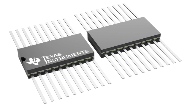
SN54LVTH240 Series
Military 8-ch, 2.7-V to 3.6-V inverters with bus-hold, TTL-compatible CMOS inputs and 3-state output
Manufacturer: Texas Instruments
Catalog
Military 8-ch, 2.7-V to 3.6-V inverters with bus-hold, TTL-compatible CMOS inputs and 3-state output
Description
AI
These octal buffers and line drivers are designed specifically for low-voltage (3.3-V) VCCoperation, but with the capability to provide a TTL interface to a 5-V system environment.
These devices are organized as two 4-bit buffer/line drivers with separate output-enable (OE)\ inputs. When OE\ is low, the devices pass data from the A inputs to the Y outputs. When OE\ is high, the outputs are in the high-impedance state.
To ensure the high-impedance state during power up or power down, OE\ should be tied to VCCthrough a pullup resistor; the minimum value of the resistor is determined by the current-sinking capability of the driver.
Active bus-hold circuitry holds unused or undriven inputs at a valid logic state. Use of pullup or pulldown resistors with the bus-hold circuitry is not recommended.
These devices are fully specified for hot-insertion applications using Ioffand power-up 3-state. The Ioffcircuitry disables the outputs, preventing damaging current backflow through the devices when they are powered down. The power-up 3-state circuitry places the outputs in the high-impedance state during power up and power down, which prevents driver conflict.
These octal buffers and line drivers are designed specifically for low-voltage (3.3-V) VCCoperation, but with the capability to provide a TTL interface to a 5-V system environment.
These devices are organized as two 4-bit buffer/line drivers with separate output-enable (OE)\ inputs. When OE\ is low, the devices pass data from the A inputs to the Y outputs. When OE\ is high, the outputs are in the high-impedance state.
To ensure the high-impedance state during power up or power down, OE\ should be tied to VCCthrough a pullup resistor; the minimum value of the resistor is determined by the current-sinking capability of the driver.
Active bus-hold circuitry holds unused or undriven inputs at a valid logic state. Use of pullup or pulldown resistors with the bus-hold circuitry is not recommended.
These devices are fully specified for hot-insertion applications using Ioffand power-up 3-state. The Ioffcircuitry disables the outputs, preventing damaging current backflow through the devices when they are powered down. The power-up 3-state circuitry places the outputs in the high-impedance state during power up and power down, which prevents driver conflict.
