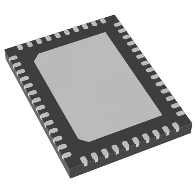
Technical Specifications
Parameters and characteristics for this part
| Specification | IPS8200HQ |
|---|---|
| Current - Output (Max) [Max] | 700 mA |
| Fault Protection | Short Circuit, Over Temperature, Over Load, UVLO |
| Interface | Parallel, Serial |
| Mounting Type | Surface Mount |
| Number of Outputs | 8 |
| Operating Temperature [Max] | 125 ¯C |
| Operating Temperature [Min] | -40 °C |
| Output Configuration | High Side |
| Package / Case | 48-VFQFN Exposed Pad |
| Rds On (Typ) | 110 mOhm |
| Supplier Device Package | 48-QFN (8x6) |
| Voltage - Load [Max] | 36 V |
| Voltage - Load [Min] | 10.5 V |
| Voltage - Supply (Vcc/Vdd) [Max] | 36 V |
| Voltage - Supply (Vcc/Vdd) [Min] | 10.5 V |
Pricing
Prices provided here are for design reference only. For realtime values and availability, please visit the distributors directly
| Distributor | Package | Quantity | $ | |
|---|---|---|---|---|
| Digikey | Cut Tape (CT) | 1 | $ 10.24 | |
| 10 | $ 9.25 | |||
| 25 | $ 8.82 | |||
| 100 | $ 7.66 | |||
| 250 | $ 7.32 | |||
| 500 | $ 6.67 | |||
| 1000 | $ 5.81 | |||
| Digi-Reel® | 1 | $ 10.24 | ||
| 10 | $ 9.25 | |||
| 25 | $ 8.82 | |||
| 100 | $ 7.66 | |||
| 250 | $ 7.32 | |||
| 500 | $ 6.67 | |||
| 1000 | $ 5.81 | |||
| Tape & Reel (TR) | 2500 | $ 5.59 | ||
Description
General part information
IPS8200HQ Series
The IPS8200HQ and IPS8200HQ -1 are monolithic 8-channel drivers, designed using STMicroelectronics™ VIPower™ technology, and intended to drive any kind of load with one side connected to the ground. Both ICs operates from 10.5 V to 36 V and feature a very low supply current, parallel or 4-wire SPI control interface, a 4x2 LED matrix, and a micropower step-down switching regulator with a peak current control loop mode.
The SPI interface (enabled by SEL2 pin = H) can work up to 5 MHz in 8-bits (SEL1 = L), or 16-bits (SEL1 = H) with a parity check and extended diagnostic (DC/DC operation, case overtemperature, SPI Communication Fail, and Power Good) information. In SPI mode the daisy chain is allowed, and both the OUT_EN signal and the MCU freeze detection by watchdog are available. If enabled (WD_EN voltage above 25% of VREG), the watchdog circuitry generates an internal reset on expiry of the internal watchdog timer. The watchdog timer reset can be achieved by applying a negative pulse on the WD pin. The watchdog timer can be programmed by the set voltage on the WD_EN pin.
The internal LED matrix driver circuitry (4 rows, 2 columns) allows the efficient driving of the 8 LEDs reporting the on/off status of each of the 8 outputs. The VREG pin supplies both the logic output buffers and LED matrix. The 100 mA output current capability of the integrated step-down (featuring overload and short-circuit conditions) can be used to supply both the VREG pin and other application components (for example: digital isolators or optocouplers).
Documents
Technical documentation and resources


