74LV32AS14-13
ActiveOR GATE, QUAD, 2 INPUT, 14 PINS, SOIC, 74LV32A
Deep-Dive with AI
Search across all available documentation for this part.
74LV32AS14-13
ActiveOR GATE, QUAD, 2 INPUT, 14 PINS, SOIC, 74LV32A
Deep-Dive with AI
Technical Specifications
Parameters and characteristics for this part
| Specification | 74LV32AS14-13 |
|---|---|
| Current - Output High, Low [custom] | 12 mA |
| Current - Output High, Low [custom] | 12 mA |
| Current - Quiescent (Max) [Max] | 20 µA |
| Input Logic Level - High | 1.5 V |
| Input Logic Level - Low | 0.5 V |
| Logic Type | OR Gate |
| Max Propagation Delay @ V, Max CL | 7.5 ns |
| Mounting Type | Surface Mount |
| Number of Circuits | 4 |
| Number of Inputs | 2 |
| Operating Temperature [Max] | 125 °C |
| Operating Temperature [Min] | -40 °C |
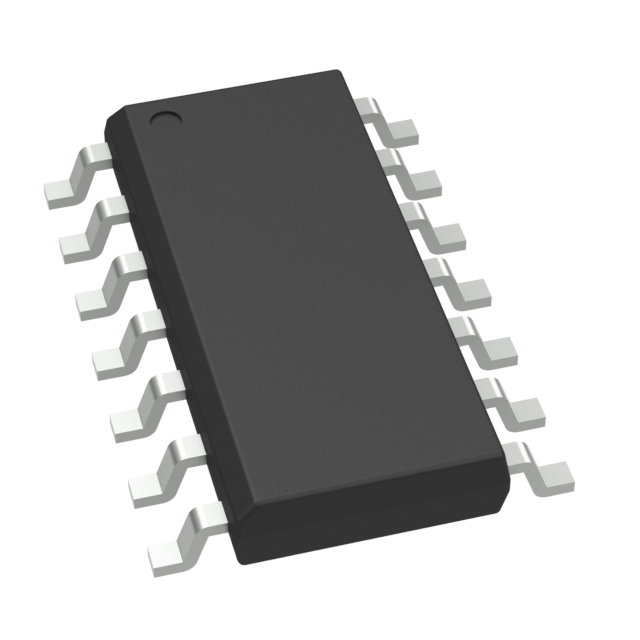
| Package / Case | 14-SOIC |
| Package / Case [x] | 0.154 in |
| Package / Case [y] | 3.9 mm |
| Supplier Device Package | 14-SO |
| Voltage - Supply [Max] | 5.5 V |
| Voltage - Supply [Min] | 2 V |
Pricing
Prices provided here are for design reference only. For realtime values and availability, please visit the distributors directly
| Distributor | Package | Quantity | $ | |
|---|---|---|---|---|
| Digikey | Cut Tape (CT) | 1 | $ 0.40 | |
| 10 | $ 0.32 | |||
| 25 | $ 0.30 | |||
| 100 | $ 0.22 | |||
| 250 | $ 0.20 | |||
| 500 | $ 0.17 | |||
| 1000 | $ 0.12 | |||
| Digi-Reel® | 1 | $ 0.40 | ||
| 10 | $ 0.32 | |||
| 25 | $ 0.30 | |||
| 100 | $ 0.22 | |||
| 250 | $ 0.20 | |||
| 500 | $ 0.17 | |||
| 1000 | $ 0.12 | |||
| Tape & Reel (TR) | 2500 | $ 0.13 | ||
| 5000 | $ 0.12 | |||
| 7500 | $ 0.11 | |||
| 12500 | $ 0.11 | |||
| 17500 | $ 0.10 | |||
| 25000 | $ 0.10 | |||
| 62500 | $ 0.09 | |||
Description
General part information
74LV32A Series
The 74LV32A provides provides four independent 2-input OR gateswith standard push-pull outputs. The device is designed for operationwith a power supply range of 2.0V to 5.5V.The inputs are tolerant to 5.5V allowing this device to be used in amixed voltage environment. The device is fully specified for partialpower down applications using IOFF. The IOFF circuitry disables theoutput preventing damaging current backflow when the device ispowered down.
Documents
Technical documentation and resources