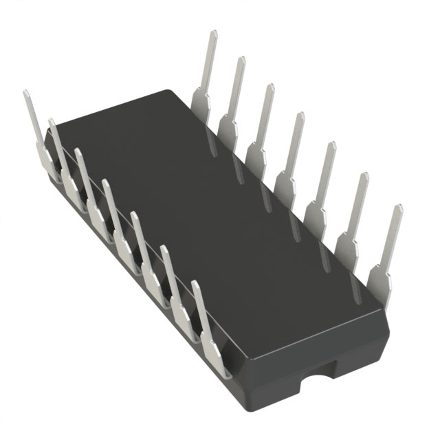
LTC1148CN-3.3#PBF
ActiveHIGH EFFICIENCY SYNCHRONOUS STEP-DOWN SWITCHING REGULATORS
Deep-Dive with AI
Search across all available documentation for this part.

LTC1148CN-3.3#PBF
ActiveHIGH EFFICIENCY SYNCHRONOUS STEP-DOWN SWITCHING REGULATORS
Deep-Dive with AI
Technical Specifications
Parameters and characteristics for this part
| Specification | LTC1148CN-3.3#PBF |
|---|---|
| Clock Sync | False |
| Control Features | Enable, Current Limit |
| Duty Cycle (Max) [Max] | 100 % |
| Frequency - Switching | 250 kHz |
| Function | Step-Down |
| Mounting Type | Through Hole |
| Number of Outputs | 1 |
| Operating Temperature [Max] | 70 °C |
| Operating Temperature [Min] | 0 °C |
| Output Configuration | Positive |
| Output Phases | 1 |
| Output Type | Transistor Driver |
| Package / Case | 14-DIP |
| Package / Case [x] | 0.3 " |
| Package / Case [y] | 7.62 mm |
| Synchronous Rectifier | True |
| Topology | Buck |
| Voltage - Supply (Vcc/Vdd) [Max] | 20 V |
| Voltage - Supply (Vcc/Vdd) [Min] | 3.5 V |
Pricing
Prices provided here are for design reference only. For realtime values and availability, please visit the distributors directly
| Distributor | Package | Quantity | $ | |
|---|---|---|---|---|
| Digikey | Tube | 75 | $ 9.29 | |
Description
General part information
LTC1148 Series
The LTC1148 series is a family of synchronous stepdown switching regulator controllers featuring automatic Burst Mode™operation to maintain high efficiencies at low output currents. These devices drive external complementary power MOSFETs at switching frequencies up to 250kHz using a constant off-time current-mode architecture providing constant ripple current in the inductor.The operating current level is user-programmable via an external current sense resistor. Wide input supply range allows operation from 3.5V to 18V (20V maximum). Constant off-time architecture provides low dropout regulation limited by only the RDS(ON)of the external MOSFET and resistance of the inductor and current sense resistor.The LTC1148 series combines synchronous switching for maximum efficiency at high currents with an automatic low current operating mode, called Burst Mode operation, which reduces switching losses. Standby power is reduced to only 2mW at VIN= 10V (at IOUT= 0). Load currents in Burst Mode operation are typically 0mA to 300mA.For operation up to 48V input, see the LTC1149 and LTC1159 data sheets and Application Note 54.ApplicationsNotebook and Palmtop ComputersPortable InstrumentsBattery-Operated Digital DevicesCellular TelephonesDC Power Distribution SystemsGPS Systems
Documents
Technical documentation and resources


