Zenode.ai Logo
BD80FC0WEFJ-E2

BD80FC0WEFJ-E2

Active
Rohm Semiconductor

1A 8V, FIXED OUTPUT, HIGH-ACCURACY LDO REGULATOR

Find alt
BD80FC0WEFJ-E2

BD80FC0WEFJ-E2

Active
Rohm Semiconductor

1A 8V, FIXED OUTPUT, HIGH-ACCURACY LDO REGULATOR

Find alt

Description

General part information

BD80FC0 Series

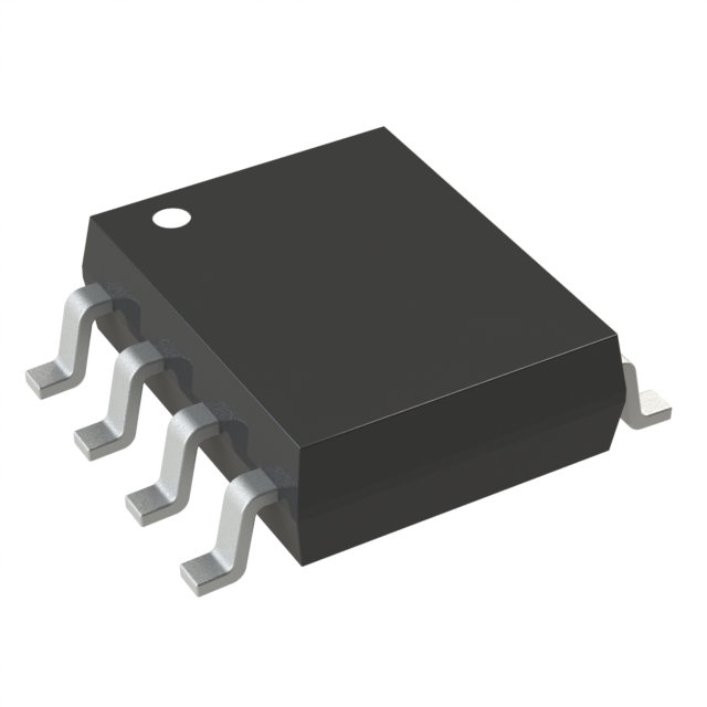
BD80FC0WEFJis low-saturation regulators. The BDxxFC0WEFJ series output voltages are Variable, 3.0V, 3.3V, 5.0V, 6.0V, 7.0V, 8.0V, 9.0V, 10.0V, 12.0V, and 15.0V and package is HTSOP-J8. This series has a built-in over-current protection circuit that prevents the destruction of the IC due to output short circuits and a thermal shutdown circuit that protects the IC from thermal damage due to overloading.

Technical Specifications

Parameters and characteristics for this part

SpecificationBD80FC0WEFJ-E2
Control FeaturesEnable
Current - Output1 A
Current - Quiescent (Iq)2.5 mA
Mounting TypeSurface Mount
Number of Regulators1
Operating Temperature (Max)85 °C
Operating Temperature (Min)-25 °C
Output ConfigurationPositive
Output TypeFixed
Package FeaturesExposed Pad
Package Length0.154 in
Package Name8-HTSOP-J, 8-SOIC
Package Width3.9 mm
Protection FeaturesOver Current, Over Temperature
Voltage - Input (Max)26.5 V
Voltage - Output (Min/Fixed)8 V
Voltage Dropout (Max)0.5 V

Pricing

Prices provided here are for design reference only. For realtime values and availability, please visit the distributors directly

Sign in to see pricing

Create a free account to access distributor pricing data.

CAD

3D models and CAD resources for this part

Documents

Technical documentation and resources

Datasheet
Basics of Linear Regulators
Thermal Calculation for Linear Regulator
Suppression Method of Switching Noise Using Linear Regulator and Low Pass Filter
EMC Measures for LDOs
PCB Layout Thermal Design Guide
Design Guide and Example of Stencil for Exposed Pad
Impedance Characteristics of Bypass Capacitor
What Is Thermal Design
θ<sub>JC</sub> and Ψ<sub>JT</sub>
Usage of SPICE Macromodel (for LDO)
Calculating Junction Temperature from Inrush Current
Anti-Whisker formation
Judgment Criteria of Thermal Evaluation
θ<sub>JA</sub> and Ψ<sub>JT</sub>
Problem Situations: Power Supply Does Not Start
How to Use the Two-Resistor Model
Solder Joint Rate and Thermal Resistance of Exposed Pad
Reverse Voltage Protection
Connecting LDOs in Parallel
Compliance with the ELV directive
Table of resistance for output voltage setting on linear regulator Ics
Basics of Thermal Resistance and Heat Dissipation
Power Source ON/OFF Characteristics for Linear Regulator
How to Select Reverse Current Protection Diodes for LDO Regulators
Precautions When Measuring the Rear of the Package with a Thermocouple
Six Steps for Successful Thermal Design of LDO Regulator ICs
Heat Dissipation Effect of Thermal Via in Exposed Pad Type Package
How to Use the Thermal Resistance and Thermal Characteristics Parameters
HTSOP-J8 Package Information
Thermal Resistance
BDxxFC0 Series PCB Layout
Power Supply Sequence Circuit with General Purpose Power Supply IC
Five Steps for Successful Thermal Design of IC
Overview of ROHM's Simulation Models(for ICs and Discrete Semiconductors)
UL94 Flame Classifications of Mold Compound
Factory Information
Method for Calculating Junction Temperature from Transient Thermal Resistance Data
Measurement Method for Phase Margin with Frequency Response Analyzer (FRA)
Simple Test Method for Estimating the Stability of Linear Regulators
BDxxFC0 Series Dropout Voltage