LTC7815HUHF#TRPBF
ActiveLOW IQ, 2.25MHZ, TRIPLE OUTPUT, BUCK/BUCK/BOOST SYNCHRONOUS CONTROLLER
Deep-Dive with AI
Search across all available documentation for this part.
LTC7815HUHF#TRPBF
ActiveLOW IQ, 2.25MHZ, TRIPLE OUTPUT, BUCK/BUCK/BOOST SYNCHRONOUS CONTROLLER
Deep-Dive with AI
Technical Specifications
Parameters and characteristics for this part
| Specification | LTC7815HUHF#TRPBF |
|---|---|
| Clock Sync | False |
| Control Features | Power Good, Tracking, Soft Start |
| Duty Cycle (Max) [Max] | 100 % |
| Frequency - Switching [Max] | 2.25 MHz |
| Frequency - Switching [Min] | 320 kHz |
| Function | Step-Up, Step-Up/Step-Down |
| Mounting Type | Surface Mount |
| Number of Outputs | 3 |
| Operating Temperature [Max] | 150 °C |
| Operating Temperature [Min] | -40 °C |
| Output Configuration | Positive |
| Output Phases | 2 |
| Output Type | Transistor Driver |
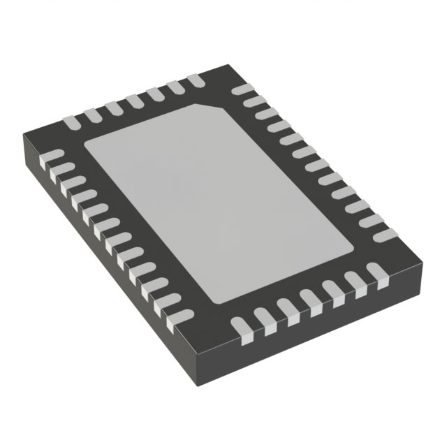
| Package / Case | 38-WFQFN Exposed Pad |
| Synchronous Rectifier | True |
| Topology | Boost, Buck |
| Voltage - Supply (Vcc/Vdd) [Max] | 38 V |
| Voltage - Supply (Vcc/Vdd) [Min] | 4.5 V |
Pricing
Prices provided here are for design reference only. For realtime values and availability, please visit the distributors directly
| Distributor | Package | Quantity | $ | |
|---|---|---|---|---|
| Digikey | Tape & Reel (TR) | 2500 | $ 7.01 | |
Description
General part information
LTC7815 Series
The LTC7815 is a high performance triple output (buck/buck/boost) synchronous DC/DC switching regulator controller that drives all N-channel power MOSFET stages. Constant frequency current mode architecture allows a phase-lockable switching frequency of up to 2.25MHz. The LTC7815 operates from a wide 4.5V to 38V input supply range. When biased from the output of the boost converter or another auxiliary supply, the LTC7815 can operate from an input supply as low as 2.5V after start-up.The 28μA no-load quiescent current extends operating runtime in battery powered systems. OPTI-LOOP compensation allows the transient response to be optimized over a wide range of output capacitance and ESR values. The LTC7815 features a precision 0.8V reference for the bucks, 1.2V reference for the boost and a power good output indicator. The PLLIN/MODE pin selects among Burst Mode operation, pulse-skipping mode, or continuous inductor current mode at light loads.ApplicationsAutomotive Always-On and Start-Stop SystemsBattery Operated Digital DevicesDistributed DC Power SystemsMultioutput Buck-Boost Applications
Documents
Technical documentation and resources