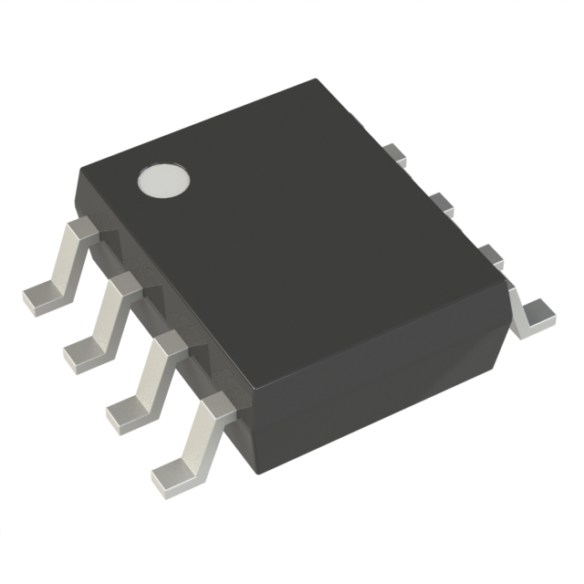
Technical Specifications
Parameters and characteristics for this part
| Specification | UC3843BD1013TR |
|---|---|
| Clock Sync | False |
| Control Features | Frequency Control |
| Duty Cycle (Max) [Max] | 96 % |
| Function | Step-Up, Step-Up/Step-Down |
| Mounting Type | Surface Mount |
| Number of Outputs | 1 |
| Operating Temperature [Max] | 70 °C |
| Operating Temperature [Min] | 0 °C |
| Output Configuration | Positive, Isolation Capable |
| Output Phases | 1 |
| Output Type | Transistor Driver |
| Package / Case | 8-SOIC |
| Package / Case [x] | 0.154 in |
| Package / Case [y] | 3.9 mm |
| Supplier Device Package | 8-SOIC |
| Synchronous Rectifier | False |
| Topology | Boost, Flyback |
| Voltage - Supply (Vcc/Vdd) [Max] | 30 V |
| Voltage - Supply (Vcc/Vdd) [Min] | 7.6 V |
Pricing
Prices provided here are for design reference only. For realtime values and availability, please visit the distributors directly
| Distributor | Package | Quantity | $ | |
|---|---|---|---|---|
| Digikey | Cut Tape (CT) | 1 | $ 0.92 | |
| 10 | $ 0.82 | |||
| 25 | $ 0.78 | |||
| 100 | $ 0.64 | |||
| 250 | $ 0.60 | |||
| 500 | $ 0.53 | |||
| 1000 | $ 0.42 | |||
| Digi-Reel® | 1 | $ 0.92 | ||
| 10 | $ 0.82 | |||
| 25 | $ 0.78 | |||
| 100 | $ 0.64 | |||
| 250 | $ 0.60 | |||
| 500 | $ 0.53 | |||
| 1000 | $ 0.42 | |||
| Tape & Reel (TR) | 2500 | $ 0.39 | ||
| 5000 | $ 0.37 | |||
| 12500 | $ 0.36 | |||
| 25000 | $ 0.35 | |||
| Newark | Each (Supplied on Cut Tape) | 1 | $ 0.89 | |
| 10 | $ 0.63 | |||
| 25 | $ 0.60 | |||
| 50 | $ 0.57 | |||
| 100 | $ 0.54 | |||
| 250 | $ 0.53 | |||
| 500 | $ 0.52 | |||
| 1000 | $ 0.51 | |||
Description
General part information
UC3843B Series
The UC284xB family of control ICs provides the necessary features to implement off-line or DC to DC fixed frequency current mode control schemes with a minimal external parts count. Internally implemented circuits include a trimmed oscillator for precise DUTY CYCLE CONTROL under voltage lockout featuring start-up current less than 0.5mA, a precision reference trimmed for accuracy at the error amp input, logic to insure latched operation, a PWM comparator which also provides current limit control, and a totem pole output stage designed to source or sink high peak current. The output stage, suitable for driving N-Channel MOSFETs, is low in the off-state.
Differences between members of this family are the under-voltage lockout thresholds and maximum duty cycle ranges. The UC2842B and UC2844B have UVLO thresholds of 16V (on) and 10V (off), ideally suited off-line applications The corresponding thresholds for the UC2843B and UC2845B are 8.5V and 7.9V. The UC2842B and UC2843B can operate to duty cycles approaching 100%. A range of the zero to < 50 % is obtained by the UC2844B and UC2845B by the addition of an internal toggle flip flop which blanks the output off every other clock cycle.
Documents
Technical documentation and resources


