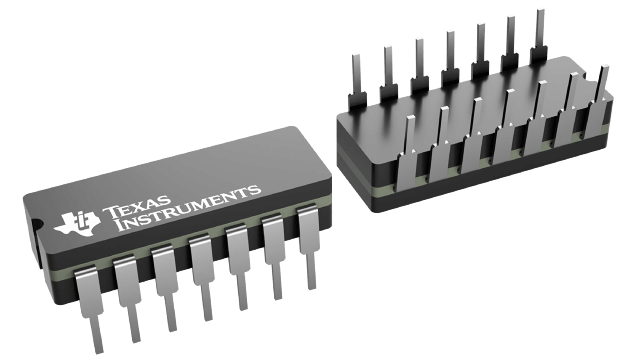
M38510/00501BCA
ActiveDUAL 2-WIDE 2-INPUT AND-OR-INVERT GATES (ONE GATE EXPANDABLE)
Deep-Dive with AI
Search across all available documentation for this part.
M38510/00501BCA
ActiveDUAL 2-WIDE 2-INPUT AND-OR-INVERT GATES (ONE GATE EXPANDABLE)
Deep-Dive with AI
Technical Specifications
Parameters and characteristics commom to parts in this series
| Specification | M38510/00501BCA | M38510 Series |
|---|---|---|
| Count Rate | - | 32 - 35 MHz |
| Direction | - | Up, Down |
| Logic Type | - | Binary Counter, Decade, Counter |
| Mounting Type | - | Surface Mount, Through Hole |
| null | - | |
| Number of Bits per Element | - | 4 |
| Number of Elements | - | 1 - 2 |
| Operating Temperature | - | -55 C |
| Operating Temperature | - | 125 °C |
| Package / Case | - | 16-CFlatPack, 20-CLCC, 14-CDIP, 16-CDIP (0.300", 7.62mm) |
| Package / Case | - | 0.3 - 7.62 in |
| Reset | - | Asynchronous |
| Supplier Device Package | - | 8.89 |
| Supplier Device Package | - | 20-LCCC, 14-CDIP, 16-CDIP |
| Supplier Device Package | - | 8.89 |
| Timing | - | Synchronous |
| Trigger Type | - | Positive Edge, Negative Edge |
| Voltage - Supply | - | 5.5 V |
| Voltage - Supply | - | 4.5 V |
Pricing
Prices provided here are for design reference only. For realtime values and availability, please visit the distributors directly
M38510 Series
Dual 4-Bit Binary Counters
| Part | Logic Type | Reset | Count Rate | Operating Temperature [Min] | Operating Temperature [Max] | Timing | Package / Case | Number of Elements [custom] | Mounting Type | Direction | Number of Bits per Element | Trigger Type | Voltage - Supply [Max] | Voltage - Supply [Min] | Supplier Device Package [y] | Supplier Device Package | Supplier Device Package [x] | Package / Case |
|---|---|---|---|---|---|---|---|---|---|---|---|---|---|---|---|---|---|---|
Texas Instruments M38510/31504BFAThese synchronous, presettable counters feature an internal carry look-ahead for application in high-speed counting designs. The '160, '162, 'LS160A, 'LS162A, and 'S162 are decade counters and the '161, '163, 'LS161A, 'LS163A, and 'S163 are 4-bit binary counters. Synchronous operation is provided by having all flip-flops clocked simultaneously so that the outputs change coincident with each other when so instructed by the count-enable inputs and internal gating. This mode of operation eliminates the output counting spikes that are normally associated with asynchronous (ripple clock) counters, however counting spikes may occur on the (RCO) ripple carry output. A buffered clock input triggers the four flip-flops on the rising edge of the clock input waveform.
These counters are fully programmable; that is, the outputs may be preset to either level. As presetting is synchronous, setting up a low level at the load input disables the counter and causes the outputs to agree with the setup data after the next clock pulse regardless of the levels of the enable inputs. Low-to-high transitions at the load input of the '160 thru '163 should be avoided when the clock is low if the enable inputs are high at or before the transition. This restriction is not applicable to the 'LS160A thru 'LS163A or 'S162 or 'S163. The clear function for the '160, '161, 'LS160A, and 'LS161A is asynchronous and a low level at the clear input sets all four of the flip-flop outputs low regardless of the levels of clock, load, or enable inputs. The clear function for the '162, '163, 'LS162A, 'LS163A, 'S162, and 'S163 is synchronous and a low level at the clear input sets all four of the flip-flop outputs low after the next clock pulse, regardless of the levels of the enable inputs. This synchronous clear allows the count length to be modified easily as decoding the maximum count desired can be accomplished with one external NAND gate. The gate output is connected to the clear input to synchronously clear the counter to 0000 (LLLL). Low-to-high transitions at the clear input of the '162 and '163 should be avoided when the clock is low if the enable and load inputs are high at or before the transition.
The carry look-ahead circuitry provides for cascading counters for n-bit synchronous applications without additional gating. Instrumental in accomplishing this function are two count-enable inputs and a ripple carry output. Both count-enable inputs (P and T) must be high to count, and input T is fed forward to enable the ripple carry output. The ripple carry output thus enabled will produce a high-level output pulse with a duration approximately equal to the high-level portion of the QAoutput. This high-level overflow ripple carry pulse can be used to enable successive cascaded stages. High-to-low level transitions at the enable P or T inputs of the '160 thru '163 should occur only when the clock input is high. Transitions at the enable P or T inputs of the 'LS160A thru 'LS163A or 'S162 and 'S163 are allowed regardless of the level of the clock input.
'LS160A thru 'LS163A, 'S162 and 'S163 feature a fully independent clock circuit. Changes at control inputs (enable P or T, or load) that will modify the operating mode have no effect until clocking occurs. The function of the counter (whether enabled, disabled, loading, or counting) will be dictated solely by the conditions meeting the stable setup and hold times.
These synchronous, presettable counters feature an internal carry look-ahead for application in high-speed counting designs. The '160, '162, 'LS160A, 'LS162A, and 'S162 are decade counters and the '161, '163, 'LS161A, 'LS163A, and 'S163 are 4-bit binary counters. Synchronous operation is provided by having all flip-flops clocked simultaneously so that the outputs change coincident with each other when so instructed by the count-enable inputs and internal gating. This mode of operation eliminates the output counting spikes that are normally associated with asynchronous (ripple clock) counters, however counting spikes may occur on the (RCO) ripple carry output. A buffered clock input triggers the four flip-flops on the rising edge of the clock input waveform.
These counters are fully programmable; that is, the outputs may be preset to either level. As presetting is synchronous, setting up a low level at the load input disables the counter and causes the outputs to agree with the setup data after the next clock pulse regardless of the levels of the enable inputs. Low-to-high transitions at the load input of the '160 thru '163 should be avoided when the clock is low if the enable inputs are high at or before the transition. This restriction is not applicable to the 'LS160A thru 'LS163A or 'S162 or 'S163. The clear function for the '160, '161, 'LS160A, and 'LS161A is asynchronous and a low level at the clear input sets all four of the flip-flop outputs low regardless of the levels of clock, load, or enable inputs. The clear function for the '162, '163, 'LS162A, 'LS163A, 'S162, and 'S163 is synchronous and a low level at the clear input sets all four of the flip-flop outputs low after the next clock pulse, regardless of the levels of the enable inputs. This synchronous clear allows the count length to be modified easily as decoding the maximum count desired can be accomplished with one external NAND gate. The gate output is connected to the clear input to synchronously clear the counter to 0000 (LLLL). Low-to-high transitions at the clear input of the '162 and '163 should be avoided when the clock is low if the enable and load inputs are high at or before the transition.
The carry look-ahead circuitry provides for cascading counters for n-bit synchronous applications without additional gating. Instrumental in accomplishing this function are two count-enable inputs and a ripple carry output. Both count-enable inputs (P and T) must be high to count, and input T is fed forward to enable the ripple carry output. The ripple carry output thus enabled will produce a high-level output pulse with a duration approximately equal to the high-level portion of the QAoutput. This high-level overflow ripple carry pulse can be used to enable successive cascaded stages. High-to-low level transitions at the enable P or T inputs of the '160 thru '163 should occur only when the clock input is high. Transitions at the enable P or T inputs of the 'LS160A thru 'LS163A or 'S162 and 'S163 are allowed regardless of the level of the clock input.
'LS160A thru 'LS163A, 'S162 and 'S163 feature a fully independent clock circuit. Changes at control inputs (enable P or T, or load) that will modify the operating mode have no effect until clocking occurs. The function of the counter (whether enabled, disabled, loading, or counting) will be dictated solely by the conditions meeting the stable setup and hold times. | Binary Counter | Asynchronous | 32 MHz | -55 C | 125 °C | Synchronous | 16-CFlatPack | 1 | Surface Mount | Up | 4 | Positive Edge | 5.5 V | 4.5 V | ||||
Texas Instruments M38510/32701B2AEach of these monolithic circuits contains eight master-slave flip-flops and additional gating to implement two individual four-bit counters in a single package. The '390 and 'LS390 incorporate dual divide-by-two and divide-by-five counters, which can be used to implement cycle lengths equal to any whole and/or cumulative multiples of 2 and/or 5 up to divide-by-100. When connected as a bi-quinary counter, the separate divide-by-two circuit can be used to provide symmetry (a square wave) at the final output stage. The '393 and 'LS393 each comprise two independent four-bit binary counters each having a clear and a clock input. N-bit binary counters can be implemented with each package providing the capability of divide-by-256. The '390, 'LS390, '393, and 'LS393 have parallel outputs from each counter stage so that any submultiple of the input count frequency is available for system-timing signals. Series 54 and Series 54LS circuits are characterized for operation over the full military temperature range of -55°C to 125°C; Series 74 and Series 74LS circuits are characterized for operation from 0°C to 70°C.
Each of these monolithic circuits contains eight master-slave flip-flops and additional gating to implement two individual four-bit counters in a single package. The '390 and 'LS390 incorporate dual divide-by-two and divide-by-five counters, which can be used to implement cycle lengths equal to any whole and/or cumulative multiples of 2 and/or 5 up to divide-by-100. When connected as a bi-quinary counter, the separate divide-by-two circuit can be used to provide symmetry (a square wave) at the final output stage. The '393 and 'LS393 each comprise two independent four-bit binary counters each having a clear and a clock input. N-bit binary counters can be implemented with each package providing the capability of divide-by-256. The '390, 'LS390, '393, and 'LS393 have parallel outputs from each counter stage so that any submultiple of the input count frequency is available for system-timing signals. Series 54 and Series 54LS circuits are characterized for operation over the full military temperature range of -55°C to 125°C; Series 74 and Series 74LS circuits are characterized for operation from 0°C to 70°C. | Counter, Decade | Asynchronous | 35 MHz | -55 C | 125 °C | 20-CLCC | 2 | Surface Mount | Up | 4 | Negative Edge | 5.5 V | 4.5 V | 8.89 | 20-LCCC | 8.89 | ||
Texas Instruments M38510/00501BCAThese devices contain two independent 2-wide 2-input AND-OR-INVERT gates with one gate expandable. They perform the Boolean function Y = (AT + CD)\ with X and X\ left open
The SN5450 ischaracterized for operation over the full military temperature range of -55°C to 125°C. The SN7450 is characterized for operation from 0°C to 70°C.
These devices contain two independent 2-wide 2-input AND-OR-INVERT gates with one gate expandable. They perform the Boolean function Y = (AT + CD)\ with X and X\ left open
The SN5450 ischaracterized for operation over the full military temperature range of -55°C to 125°C. The SN7450 is characterized for operation from 0°C to 70°C. | ||||||||||||||||||
Texas Instruments M38510/07002BCAThese devices contain four independent 2-input-NAND gates. The open-collector outputs require pull-up resistors to perform correctly. They may be connected to other open-collector outputs to implement active-low wired-OR or active-high wired-AND functions. Open-collector devices are often used to generate higher VOHlevels.
The SN5403, SN54LS03 and SN54S03 are characterized for operation over the full military temperature range of -55°C to 125°C. The SN7403, SN74LS03 and SN74S03 are characterized for operation from 0°C to 70°C.
These devices contain four independent 2-input-NAND gates. The open-collector outputs require pull-up resistors to perform correctly. They may be connected to other open-collector outputs to implement active-low wired-OR or active-high wired-AND functions. Open-collector devices are often used to generate higher VOHlevels.
The SN5403, SN54LS03 and SN54S03 are characterized for operation over the full military temperature range of -55°C to 125°C. The SN7403, SN74LS03 and SN74S03 are characterized for operation from 0°C to 70°C. | ||||||||||||||||||
Texas Instruments M38510/32702BCAEach of these monolithic circuits contains eight master-slave flip-flops and additional gating to implement two individual four-bit counters in a single package. The '390 and 'LS390 incorporate dual divide-by-two and divide-by-five counters, which can be used to implement cycle lengths equal to any whole and/or cumulative multiples of 2 and/or 5 up to divide-by-100. When connected as a bi-quinary counter, the separate divide-by-two circuit can be used to provide symmetry (a square wave) at the final output stage. The '393 and 'LS393 each comprise two independent four-bit binary counters each having a clear and a clock input. N-bit binary counters can be implemented with each package providing the capability of divide-by-256. The '390, 'LS390, '393, and 'LS393 have parallel outputs from each counter stage so that any submultiple of the input count frequency is available for system-timing signals. Series 54 and Series 54LS circuits are characterized for operation over the full military temperature range of -55°C to 125°C; Series 74 and Series 74LS circuits are characterized for operation from 0°C to 70°C.
Each of these monolithic circuits contains eight master-slave flip-flops and additional gating to implement two individual four-bit counters in a single package. The '390 and 'LS390 incorporate dual divide-by-two and divide-by-five counters, which can be used to implement cycle lengths equal to any whole and/or cumulative multiples of 2 and/or 5 up to divide-by-100. When connected as a bi-quinary counter, the separate divide-by-two circuit can be used to provide symmetry (a square wave) at the final output stage. The '393 and 'LS393 each comprise two independent four-bit binary counters each having a clear and a clock input. N-bit binary counters can be implemented with each package providing the capability of divide-by-256. The '390, 'LS390, '393, and 'LS393 have parallel outputs from each counter stage so that any submultiple of the input count frequency is available for system-timing signals. Series 54 and Series 54LS circuits are characterized for operation over the full military temperature range of -55°C to 125°C; Series 74 and Series 74LS circuits are characterized for operation from 0°C to 70°C. | Binary Counter | Asynchronous | 35 MHz | -55 C | 125 °C | 14-CDIP | 2 | Through Hole | Up | 4 | Negative Edge | 5.5 V | 4.5 V | 14-CDIP | 0.3 in, 7.62 mm | |||
Texas Instruments M38510/31508BEAThese monolithic circuits are synchronous reversible (up/down) counters having a complexity of 55 equivalent gates. The '192 and 'LS192 circuits are BCD counters and the '193 and 'LS193 are 4-bit binary counters. Synchronous operation is provided by having all flip-flops clocked simultaneously so that the outputs change coincidently with each other when so instructed by the steering logic. This mode of operation eliminates the output counting spikes which are normally associated with asynchronous (ripple-clock) counters.
The outputs of the four master-slave flip-flops are triggered by a low-to-high-level transition of either count (clock) input. The direction of counting is determined by which count input is pulsed while the other count input is high.
All four counters are fully programmable; that is, each output may be preset to either level by entering the desired data at the data inputs while the load input is low. The output will change to agree with the data inputs independently of the count pulses. This feature allows the counters to be used as modulo-N dividers by simply modifying the count length with the preset inputs.
A clear input has been provided which forces all outputs to the low level when a high level is applied. The clear function is independent of the count and load inputs. The clear, count, and load inputs are buffered to lower the drive requirements. This reduces the number of clock drivers etc., required for long words.
These counters are designed to be cascaded without the need for external circuitry. Both borrow and carry outputs are available to cascade both the up- and down-counting functions. The borrow output produces a pulse equal in width to the count-down input when the counter underflows. Similarly, the carry output produces a pulse equal in width to the count-up input when an overflow condition exists. The counters can then be easily cascaded by feeding the borrow and carry outputs to the count-down and count-up inputs respectively of the succeeding counter.
These monolithic circuits are synchronous reversible (up/down) counters having a complexity of 55 equivalent gates. The '192 and 'LS192 circuits are BCD counters and the '193 and 'LS193 are 4-bit binary counters. Synchronous operation is provided by having all flip-flops clocked simultaneously so that the outputs change coincidently with each other when so instructed by the steering logic. This mode of operation eliminates the output counting spikes which are normally associated with asynchronous (ripple-clock) counters.
The outputs of the four master-slave flip-flops are triggered by a low-to-high-level transition of either count (clock) input. The direction of counting is determined by which count input is pulsed while the other count input is high.
All four counters are fully programmable; that is, each output may be preset to either level by entering the desired data at the data inputs while the load input is low. The output will change to agree with the data inputs independently of the count pulses. This feature allows the counters to be used as modulo-N dividers by simply modifying the count length with the preset inputs.
A clear input has been provided which forces all outputs to the low level when a high level is applied. The clear function is independent of the count and load inputs. The clear, count, and load inputs are buffered to lower the drive requirements. This reduces the number of clock drivers etc., required for long words.
These counters are designed to be cascaded without the need for external circuitry. Both borrow and carry outputs are available to cascade both the up- and down-counting functions. The borrow output produces a pulse equal in width to the count-down input when the counter underflows. Similarly, the carry output produces a pulse equal in width to the count-up input when an overflow condition exists. The counters can then be easily cascaded by feeding the borrow and carry outputs to the count-down and count-up inputs respectively of the succeeding counter. | Binary Counter | Asynchronous | 32 MHz | -55 C | 125 °C | Synchronous | 16-CDIP (0.300", 7.62mm) | 1 | Through Hole | Down, Up | 4 | Positive Edge | 5.5 V | 4.5 V | 16-CDIP | |||
Texas Instruments M38510/30007BDAThese devices contain two independent 4-input NAND gates.
The SN5420, SN54LS20, and SN54S20 are characterized for operation over the full military range of -55°C to 125°C. The SN7420, SN74LS20, and SN74S20 are characterized for operation from 0°C to 70°C.
These devices contain two independent 4-input NAND gates.
The SN5420, SN54LS20, and SN54S20 are characterized for operation over the full military range of -55°C to 125°C. The SN7420, SN74LS20, and SN74S20 are characterized for operation from 0°C to 70°C. |
Description
General part information
M38510 Series
Each of these monolithic circuits contains eight master-slave flip-flops and additional gating to implement two individual four-bit counters in a single package. The '390 and 'LS390 incorporate dual divide-by-two and divide-by-five counters, which can be used to implement cycle lengths equal to any whole and/or cumulative multiples of 2 and/or 5 up to divide-by-100. When connected as a bi-quinary counter, the separate divide-by-two circuit can be used to provide symmetry (a square wave) at the final output stage. The '393 and 'LS393 each comprise two independent four-bit binary counters each having a clear and a clock input. N-bit binary counters can be implemented with each package providing the capability of divide-by-256. The '390, 'LS390, '393, and 'LS393 have parallel outputs from each counter stage so that any submultiple of the input count frequency is available for system-timing signals. Series 54 and Series 54LS circuits are characterized for operation over the full military temperature range of -55°C to 125°C; Series 74 and Series 74LS circuits are characterized for operation from 0°C to 70°C.
Each of these monolithic circuits contains eight master-slave flip-flops and additional gating to implement two individual four-bit counters in a single package. The '390 and 'LS390 incorporate dual divide-by-two and divide-by-five counters, which can be used to implement cycle lengths equal to any whole and/or cumulative multiples of 2 and/or 5 up to divide-by-100. When connected as a bi-quinary counter, the separate divide-by-two circuit can be used to provide symmetry (a square wave) at the final output stage. The '393 and 'LS393 each comprise two independent four-bit binary counters each having a clear and a clock input. N-bit binary counters can be implemented with each package providing the capability of divide-by-256. The '390, 'LS390, '393, and 'LS393 have parallel outputs from each counter stage so that any submultiple of the input count frequency is available for system-timing signals. Series 54 and Series 54LS circuits are characterized for operation over the full military temperature range of -55°C to 125°C; Series 74 and Series 74LS circuits are characterized for operation from 0°C to 70°C.
Documents
Technical documentation and resources