Zenode.ai Logo
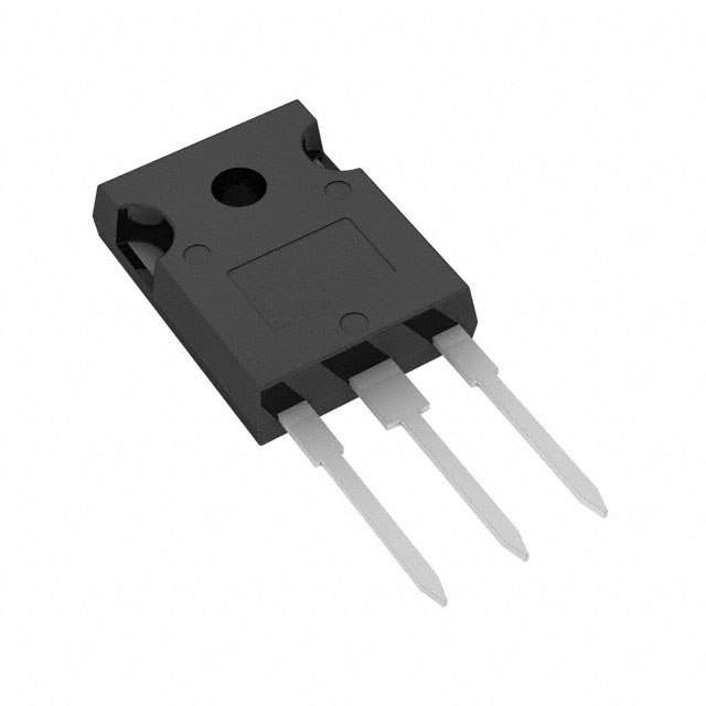
SCT3030KLHRC11

SCT3030KLHRC11

Active
Rohm Semiconductor

1200V, 72A, THD, TRENCH-STRUCTURE, SILICON-CARBIDE (SIC) MOSFET FOR AUTOMOTIVE

Find alt
SCT3030KLHRC11

SCT3030KLHRC11

Active
Rohm Semiconductor

1200V, 72A, THD, TRENCH-STRUCTURE, SILICON-CARBIDE (SIC) MOSFET FOR AUTOMOTIVE

Find alt

Description

General part information

SCT3030 Series

SCT3030AR is anSiC MOSFETfeaturing a trench gate structure optimized for server power supplies, motor drives, solar power inverters, andEV charging stationsrequiring high efficiency. A new 4-pin package is used that separates the power and driver source terminals, making it possible to maximize high-speed switching performance. This improves turn ON loss in particular, and as a result, the total turn ON and turn OFF losses can be reduced by as much as 35% compared with the conventional 3-pin package (TO-247N).A pioneer and industry leader in SiC technology, ROHM was the first supplier to mass produce trench-type MOSFETs that further improve efficiency while reducing power consumption over existing SiC MOSFETs.

Technical Specifications

Parameters and characteristics for this part

SpecificationSCT3030KLHRC11
Current - Continuous Drain (Id) (Tc)72 A
Drain to Source Voltage (Vdss)1200 V
Drive Voltage (Max Rds On, Min Rds On)18 V
FET TypeN-Channel
Gate Charge (Max)131 nC
GradeAutomotive
Input Capacitance (Ciss) (Max)2222 pF
Mounting TypeThrough Hole
Operating Temperature175 °C
Package / CaseTO-247-3
Package NameTO-247N
Power Dissipation (Max)339 W
QualificationAEC-Q101
Rds On (Max)39 mOhm
TechnologySiCFET (Silicon Carbide)
Vgs (Max) Negative-4 V
Vgs (Max) Positive22 V
Vgs(th) (Max)5.6 V

Pricing

Prices provided here are for design reference only. For realtime values and availability, please visit the distributors directly

Sign in to see pricing

Create a free account to access distributor pricing data.

CAD

3D models and CAD resources for this part

Documents

Technical documentation and resources
Judgment Criteria of Thermal Evaluation
How to Use PSIM Models
LEADRIVE: Design, Test and System Evaluation of Silicon Carbide Power Modules and Motor Control Units
Importance of Probe Calibration When Measuring Power: Deskew
About Flammability of Materials
Method for Calculating Junction Temperature from Transient Thermal Resistance Data
Example of Heat Dissipation Design for TO Packages: Effect of Heat Dissipation Materials
PCB Layout Thermal Design Guide
How to Use the Thermal Resistance and Thermal Characteristics Parameters
Calculating Power Loss from Measured Waveforms
SCT3030KLHR Data Sheet
How to Suppress the Parallel Drive Oscillation in SiC Modules
Notes on Gate Drive Voltage Setting and Linear Mode Application of SiC MOSFET
How to Use PLECS Models
800V Three-Phase Output LLC DC/DC Resonant Converter
Part Explanation
Precautions for Thermal Resistance of Insulation Sheet
Gate-Source Voltage Surge Suppression Methods
Basics and Design Guidelines for Gate Drive Circuits
Types and Features of Transistors
Precautions during gate-source voltage measurement for SiC MOSFET
Design Method for Comparator-less Miller Clamp Circuits
What is a Thermal Model? (SiC Power Device)
Simulation Verification to Identify Oscillation between Parallel Dies during Design Phase of Power Modules
θ<sub>JA</sub> and Ψ<sub>JT</sub>
Application Note for SiC Power Devices and Modules
About Export Administration Regulations (EAR)
Basics of Thermal Resistance and Heat Dissipation
Package Dimensions
How to Create Symbols for PSpice Models
Measurement Method and Usage of Thermal Resistance RthJC
How to Use Thermal Models
Compliance of the ELV directive
Notes for Calculating Power Consumption:Static Operation
Calculation of Power Dissipation in Switching Circuit
Generation Mechanism of Voltage Surge on Commutation Side (Basic)
Gate-source voltage behaviour in a bridge configuration
Oscillation countermeasures for MOSFETs in parallel
Overview of ROHM's Simulation Models(for ICs and Discrete Semiconductors)
How to Use LTspice&reg; Models: Tips for Improving Convergence
How to measure the oscillation occurs between parallel-connected devices
Thermal Resistance Measurement Method for SiC MOSFET
θ<sub>JC</sub> and Ψ<sub>JT</sub>
Impedance Characteristics of Bypass Capacitor
5kW High-Efficiency Fan-less Inverter
What Is Thermal Design
Anti-Whisker formation
Explanation for Marking - TO-247N SiC_Marking-e.pdf
Method for Monitoring Switching Waveform
Notes for Temperature Measurement Using Forward Voltage of PN Junction
Condition of Soldering
The Problem with Traditional Vaccine Storage Freezers and How ROHM Cutting-edge Power Solutions Can Take them to the Next Level
Solving the challenges of driving SiC MOSFETs with new packaging developments
4 Steps for Successful Thermal Designing of Power Devices
Power Eco Family: Overview of ROHM's Power Semiconductor Lineup
Best practices for the connection of Driver Source/Emitter terminals in discrete devices
Precautions When Measuring the Rear of the Package with a Thermocouple
SiC MOSFET Layout Design Considerations
Snubber circuit design methods for SiC MOSFET
Two-Resistor Model for Thermal Simulation
Notes for Temperature Measurement Using Thermocouples
Cutting-Edge Web Simulation Tool "ROHM Solution Simulator" Capable of Complete Circuit Verification of Power Devices and Driver ICs
Taping Information
How to Use LTspice&reg; Models
SCT PPAP Statement