Technical Specifications
Parameters and characteristics for this part
| Specification | EVLSRK1001-TO |
|---|---|
| Contents | Board(s) |
| Function | Gate Driver |
| Supplied Contents | Board(s) |
| Type | Power Management |
| Utilized IC / Part | EVLSRK1001 |
EVLSRK1001-TO Series
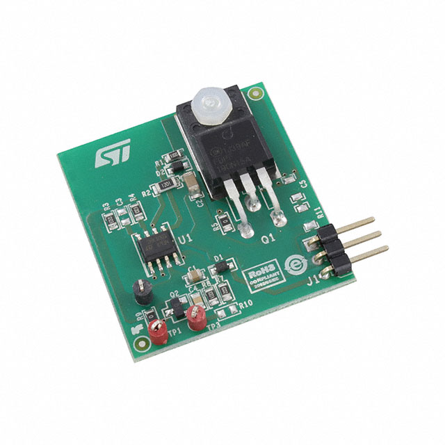
SRK1001 adaptive synchronous rectification controller for flyback converter demonstration board with SR MOSFET
| Part | Utilized IC / Part | Function | Supplied Contents | Contents | Type |
|---|---|---|---|---|---|
STMicroelectronics | SRK1001 | Gate Driver | Board(s) | Board(s) | Power Management |
STMicroelectronics | EVLSRK1001 | Gate Driver | Board(s) | Board(s) | Power Management |
Pricing
Prices provided here are for design reference only. For realtime values and availability, please visit the distributors directly
Description
General part information
EVLSRK1001-TO Series
The EVLSRK1001-PF is a demonstration board, designed for evaluation of the SRK1001 synchronous rectification controller. The SRK1001 implements a control scheme specific for secondary-side synchronous rectification in flyback converters and provides high-current gate-drive outputs for driving N-channel Power MOSFET. The device can operate both in quasi-resonant (QR) applications and in fixed frequency (FF) mixed DCM-CCM applications. The board is provided with a setting suitable for QR application. To use in FF applications, a 100pF capacitor needs to be added in C3. A 120 kΩ resistor (R3) is provided on the TON pin that fixes the blanking after the turn-on to about 1.44 µs. The blanking time after turn-off is set to 3 μs through a 100 kΩ resistor (R4) on TOFF pin. In order to use the DIS/SYNC pin functionality, the user has to remove the zero ohm resistor R9: the PCB already provides a NPN transistor connected to this pin for remote ON/OFF. The board includes the SR MOSFET (PowFLAT 5 x 6 package) and can be easily implemented into an existing converter to substitute rectifier diodes.
Documents
Technical documentation and resources