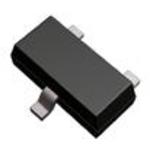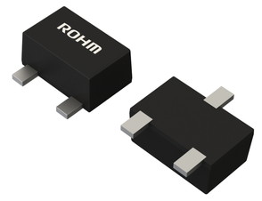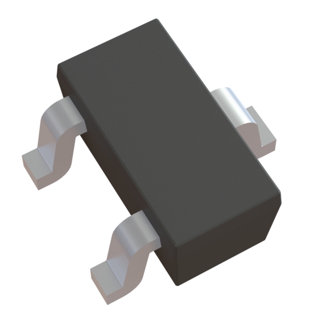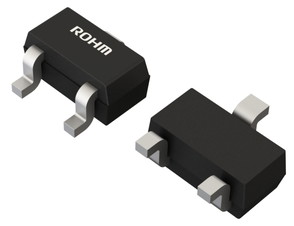
DTA114EEFRATL
ActivePNP, SOT-416, R1=R2 POTENTIAL DIVIDER TYPE DIGITAL TRANSISTOR (BIAS RESISTOR BUILT-IN TRANSISTOR) FOR AUTOMOTIVE
DTA114EEFRATL
ActivePNP, SOT-416, R1=R2 POTENTIAL DIVIDER TYPE DIGITAL TRANSISTOR (BIAS RESISTOR BUILT-IN TRANSISTOR) FOR AUTOMOTIVE
Description
General part information
DTA114 Series
DTA114TU3HZG is an digital transistor (Resistor built-in type transistor). Built-in bias resistors enable the configuration of an inverter circuit without connecting external input resistors. This is a high-reliability product of automotive grade qualified to AEC-Q101.
Technical Specifications
Parameters and characteristics for this part
| Specification | DTA114EEFRATL |
|---|---|
| Current - Collector (Ic) (Max) | 20 mA |
| Current - Collector Cutoff (Max) | 500 nA |
| DC Current Gain (hFE) (Min) | 20 |
| Frequency - Transition | 250 MHz |
| Grade | Automotive |
| Mounting Type | Surface Mount |
| Package / Case | SOT-416, SC-75 |
| Package Name | EMT3 |
| Power - Max | 150 mW |
| Qualification | AEC-Q101 |
| Resistor - Base (R1) Resistance | 10 kOhm |
| Resistor - Emitter Base (R2) | 10 kOhms |
| Transistor Type | Pre-Biased, PNP |
| Vce Saturation (Max) | 300 mV |
| Voltage - Collector Emitter Breakdown (Max) | 50 V |
Pricing
Prices provided here are for design reference only. For realtime values and availability, please visit the distributors directly
Sign in to see pricing
Create a free account to access distributor pricing data.
CAD
3D models and CAD resources for this part
Documents
Technical documentation and resources