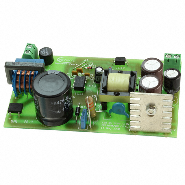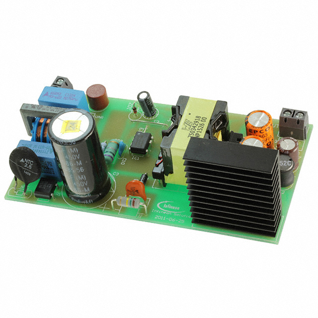
EVALQRCICE2QR0680ZTOBO1
Unknown40W SWITCHING MODE POWER SUPPLY EVALUATION BOARD DESIGNED IN A QUASI RESONANT FLYBACK CONVERTER TOPOLOGY USING ICE2QR0680Z QUASI-RESONANT COOLSET™. WITH THE COOLMOS™ INTEGRATED IN THIS IC, IT GREATLY SIMPLIFIES THE DESIGN AND LAYOUT OF THE PCB. DUE TO VALLEY SWITCHING, THE TURN ON VOLTAGE IS REDUCED AND THIS OFFERS HIGHER CONVERSION EFFICIENCY COMPARING TO HARD-SWITCHING FLYBACK CONVERTER.
EVALQRCICE2QR0680ZTOBO1
Unknown40W SWITCHING MODE POWER SUPPLY EVALUATION BOARD DESIGNED IN A QUASI RESONANT FLYBACK CONVERTER TOPOLOGY USING ICE2QR0680Z QUASI-RESONANT COOLSET™. WITH THE COOLMOS™ INTEGRATED IN THIS IC, IT GREATLY SIMPLIFIES THE DESIGN AND LAYOUT OF THE PCB. DUE TO VALLEY SWITCHING, THE TURN ON VOLTAGE IS REDUCED AND THIS OFFERS HIGHER CONVERSION EFFICIENCY COMPARING TO HARD-SWITCHING FLYBACK CONVERTER.
Description
General part information
EVALQRCICE2 Series
40W 20V Evaluation Board with Quasi-Resonant CoolSET™ ICE2QR0680Z 40W switching mode power supply evaluation board designed in a quasi resonant flyback converter topology usingICE2QR0680ZQuasi-resonant CoolSET™. With the CoolMOS™ integrated in this IC, it greatly simplifies the design and layout of the PCB. Due to valley switching, the turn on voltage is reduced and this offers higher conversion efficiency comparing to hard-switching flyback converter. With the DCM mode control, the reverse recovery problem of secondary rectify diode is relieved. And for its natural frequency jittering with line voltage, the EMI performance is better. Infineon’s digital frequency reduction technology enables a quasi-resonant operation till very low load. As a result, the system efficiency, over the entire load range, is significantly improved compared to conventional free running quasi resonant converter implemented with only maximum switching frequency limitation at light load. In addition, numerous adjustable protection functions have been implemented in ICE2QR0680Z to protect the system and customize the IC for the chosen application. In case of failure modes, like open control-loop/over load, output overvoltage, and transformer short winding, the device switches into Auto Restart Mode or Latch-off Mode. By means of the cycle-by-cycle peak current limitation plus foldback point correction, the dimension of the transformer and current rating of the secondary diode can both be optimized.Thus, a cost effective solution can be easily achieved.
Technical Specifications
Parameters and characteristics for this part
| Specification | EVALQRCICE2QR0680ZTOBO1 |
|---|---|
| Board Type | Fully Populated |
| Contents | Board |
| Frequency - Switching | 100 kHz |
| Isolated Output Count | 1 |
| Main Purpose | Primary Side, AC/DC |
| Output Type | Isolated |
| Power - Output | 40 W |
| Regulator Topology | Flyback |
| Supplied Contents | Board(s) |
| Total Output Count | 1 |
| Utilized IC / Part | ICE2QR0680Z |
| Voltage - Input (AC) Maximum | 265 VAC |
| Voltage - Input (AC) Minimum | 85 VAC |
| Voltage - Output | 20 V |
Pricing
Prices provided here are for design reference only. For realtime values and availability, please visit the distributors directly
Sign in to see pricing
Create a free account to access distributor pricing data.
CAD
3D models and CAD resources for this part
Documents
Technical documentation and resources