


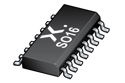
74HCT193D-Q100J
ActiveCOUNTER, PRESETTABLE BINARY, SYNCHRONOUS, UP / DOWN, 74HCT, 43 MHZ, MAX COUNT 15, 4.5 V TO 5.5 V, 16… MORE

74HCT193D-Q100J
ActiveCOUNTER, PRESETTABLE BINARY, SYNCHRONOUS, UP / DOWN, 74HCT, 43 MHZ, MAX COUNT 15, 4.5 V TO 5.5 V, 16… MORE
Description
General part information
74HCT193D-Q100 Series
The 74HC193-Q100; 74HCT193-Q100 is a 4-bit synchronous binary up/down counter. Separate up/down clocks, CPU and CPD respectively, simplify operation. The outputs change state synchronously with the LOW-to-HIGH transition of either clock input. If the CPU clock is pulsed while CPD is held HIGH, the device counts up. If the CPD clock is pulsed while CPU is held HIGH, the device counts down. Only one clock input can be held HIGH at any time to guarantee predictable behavior. The device can be cleared at any time by the asynchronous master reset input (MR). It may also be loaded in parallel by activating the asynchronous parallel load input (PL). The terminal count up (TCU) and terminal count down (TCD) outputs are normally HIGH. When the circuit has reached the maximum count state of 15, the next HIGH-to-LOW transition of CPU causesTCUto go LOW.TCUremains LOW until CPU goes HIGH again, duplicating the count up clock. Likewise, theTCDoutput goes LOW when the circuit is in the zero state and the CPD goes LOW. The terminal count outputs duplicate the clock waveforms and can be used as the clock input signals to the next higher-order circuit in a multistage counter. Multistage counters are not fully synchronous, since there is a slight delay time difference added for each stage that is added. The counter may be preset by the asynchronous parallel load capability of the circuit. Information on the parallel data inputs (D0 to D3), is loaded into the counter. This information appears on the outputs (Q0 to Q3) regardless of the conditions of the clock inputs when the parallel load (PL) input is LOW. A HIGH level on the master reset (MR) input disables the parallel load gates. It overrides both clock inputs and sets all outputs (Q0 to Q3) LOW. If one of the clock inputs is LOW during and after a reset or load operation, the next LOW-to-HIGH transition of that clock is interpreted as a legitimate signal and it is counted. Inputs include clamp diodes that enable the use of current limiting resistors to interface inputs to voltages in excess of VCC.
Technical Specifications
Parameters and characteristics for this part
| Specification | 74HCT193D-Q100J |
|---|---|
| Count Rate | 43 MHz |
| Direction | Up, Down |
| Grade | Automotive |
| Logic Type | Binary Counter |
| Mounting Type | Surface Mount |
| Number of Bits per Element | 4 bits |
| Number of Elements | 1 |
| Operating Temperature (Max) | 125 °C |
| Operating Temperature (Min) | -40 °C |
| Package Length | 0.154 in |
| Package Name | 16-SO, 16-SOIC |
| Package Width | 3.9 mm |
| Qualification | AEC-Q100 |
| Reset | Asynchronous |
| Timing | Synchronous |
| Trigger Type | Positive Edge |
| Voltage - Supply (Maximum) | 5.5 V |
| Voltage - Supply (Minimum) | 4.5 V |
Pricing
Prices provided here are for design reference only. For realtime values and availability, please visit the distributors directly
Sign in to see pricing
Create a free account to access distributor pricing data.
CAD
3D models and CAD resources for this part
Documents
Technical documentation and resources