


BD42540FJ-CE2
Active70MA, LOW IQ VOLTAGE TRACKER FOR AUTOMOTIVE

BD42540FJ-CE2
Active70MA, LOW IQ VOLTAGE TRACKER FOR AUTOMOTIVE
Description
General part information
BD42540FJ-C Series
The BD42540FJ-C is low quiescent regulator featuring 45V absolute maximum voltage, and output voltage tracking accuracy of ±10mV, 70mA output current and 40µA (typ.) current consumption. This tracker is therefore ideal for applications requiring a direct connection to the battery and a low current consumption. Ceramic capacitors can be used for compensation of the output capacitor phase. Furthermore, this IC also feature overcurrent protection to protect the device from damage caused by short-circuiting and an integrated thermal shutdown to protect the device from overheating at overload conditions.
Technical Specifications
Parameters and characteristics for this part
| Specification | BD42540FJ-CE2 |
|---|---|
| Control Features | Enable |
| Current - Output | 70 mA |
| Current - Supply (Max) | 80 µA |
| Grade | Automotive |
| Mounting Type | Surface Mount |
| Number of Regulators | 1 |
| Operating Temperature (Max) | 125 °C |
| Operating Temperature (Min) | -40 °C |
| Output Configuration | Positive |
| Output Type | Adjustable (Fixed) |
| Package Length | 0.154 in |
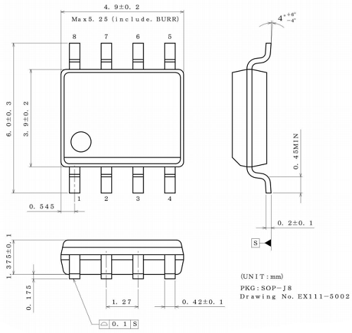
| Package Name | 8-SOP-J, 8-SOIC |
| Package Width | 3.9 mm |
| Protection Features | Over Current, Over Temperature |
| PSRR | 80 dB |
| Qualification | AEC-Q100 |
| Voltage - Input (Max) | 42 V |
| Voltage Dropout (Max) | 0.4 V |
Pricing
Prices provided here are for design reference only. For realtime values and availability, please visit the distributors directly
Sign in to see pricing
Create a free account to access distributor pricing data.
CAD
3D models and CAD resources for this part
Documents
Technical documentation and resources