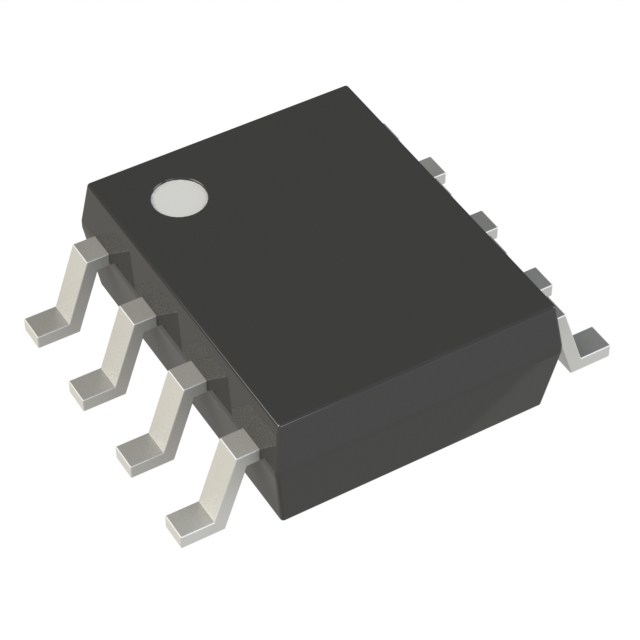
Technical Specifications
Parameters and characteristics for this part
| Specification | TD352IDT |
|---|---|
| Channel Type | Single |
| Current - Peak Output (Source, Sink) [custom] | 1.7 A |
| Current - Peak Output (Source, Sink) [custom] | 1.3 A |
| Driven Configuration | High-Side |
| Gate Type | IGBT, MOSFET |
| Input Type | Non-Inverting |
| Logic Voltage - VIL, VIH | 4.2 V, 0.8 V |
| Mounting Type | Surface Mount |
| Number of Drivers | 1 |
| Operating Temperature [Max] | 150 °C |
| Operating Temperature [Min] | -40 °C |
| Package / Case | 8-SOIC |
| Package / Case [x] | 0.154 in |
| Package / Case [y] | 3.9 mm |
| Rise / Fall Time (Typ) | 100 ns |
| Rise / Fall Time (Typ) [Max] | 100 ns |
| Supplier Device Package | 8-SOIC |
| Voltage - Supply [Max] | 26 V |
| Voltage - Supply [Min] | 12 V |
Pricing
Prices provided here are for design reference only. For realtime values and availability, please visit the distributors directly
| Distributor | Package | Quantity | $ | |
|---|---|---|---|---|
| Digikey | Cut Tape (CT) | 1 | $ 2.62 | |
| 10 | $ 1.95 | |||
| 25 | $ 1.78 | |||
| 100 | $ 1.60 | |||
| 250 | $ 1.51 | |||
| 500 | $ 1.46 | |||
| 1000 | $ 1.41 | |||
| Digi-Reel® | 1 | $ 2.62 | ||
| 10 | $ 1.95 | |||
| 25 | $ 1.78 | |||
| 100 | $ 1.60 | |||
| 250 | $ 1.51 | |||
| 500 | $ 1.46 | |||
| 1000 | $ 1.41 | |||
| Tape & Reel (TR) | 2500 | $ 1.24 | ||
| Newark | Each (Supplied on Cut Tape) | 1 | $ 2.03 | |
| 10 | $ 1.67 | |||
| 25 | $ 1.57 | |||
| 50 | $ 1.53 | |||
| 100 | $ 1.50 | |||
| 250 | $ 1.45 | |||
| 500 | $ 1.41 | |||
| 1000 | $ 1.37 | |||
Description
General part information
TD352 Series
This device is an advanced gate driver for IGBTs and power MOSFETs. Control and protection functions are included and allow the design of high reliability systems.
The innovative active Miller clamp function eliminates the need for negative gate drive in most applications and allows the use of a simple bootstrap supply for the high side driver.
The TD352 includes an adjustable turn-on delay. This feature can be used to implement reliable deadtime between high and low sides of a half bridge. An external resistor and capacitor are used to provide accurate timing.
Documents
Technical documentation and resources


