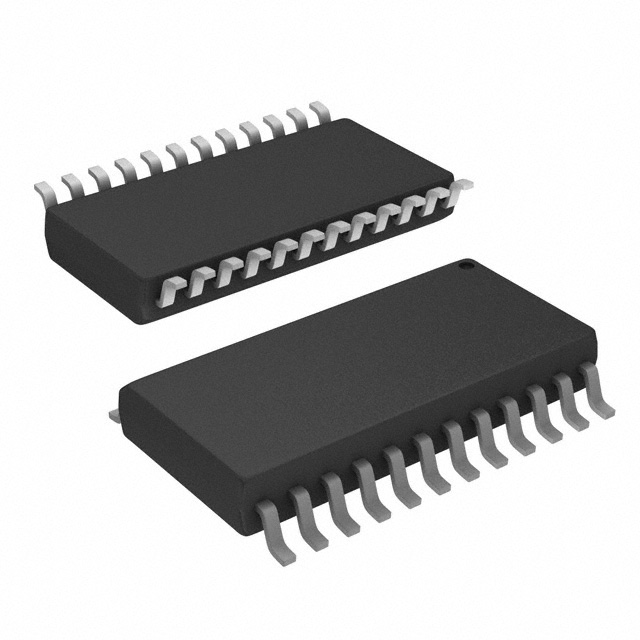
E-L6219R
ActiveIC MTR DRV BIPLR 4.75-5.25V 24SO
Deep-Dive with AI
Search across all available documentation for this part.

E-L6219R
ActiveIC MTR DRV BIPLR 4.75-5.25V 24SO
Deep-Dive with AI
Technical Specifications
Parameters and characteristics for this part
| Specification | E-L6219R |
|---|---|
| Applications | General Purpose |
| Current - Output | 500 mA |
| Function | Driver - Fully Integrated, Control and Power Stage |
| Interface | Parallel |
| Motor Type - AC, DC | Brushed DC |
| Motor Type - Stepper | Bipolar |
| Mounting Type | Surface Mount |
| Operating Temperature [Max] | 150 °C |
| Operating Temperature [Min] | -20 °C |
| Output Configuration | Half Bridge (4) |
| Package / Case | 24-SOIC |
| Package / Case [custom] | 7.5 mm |
| Package / Case [custom] | 0.295 in |
| Step Resolution | 1, 0.5 |
| Supplier Device Package | 24-SO |
| Voltage - Load [Max] | 10 V |
| Voltage - Load [Min] | 4.5 V |
| Voltage - Supply [Max] | 5.25 V |
| Voltage - Supply [Min] | 4.75 V |
Pricing
Prices provided here are for design reference only. For realtime values and availability, please visit the distributors directly
| Distributor | Package | Quantity | $ | |
|---|---|---|---|---|
| Digikey | Tube | 1 | $ 3.44 | |
| 10 | $ 2.27 | |||
| 25 | $ 1.96 | |||
| 100 | $ 1.62 | |||
| 250 | $ 1.45 | |||
| 500 | $ 1.35 | |||
| 1000 | $ 1.29 | |||
Description
General part information
L6219DSA Series
The L6219R is a bipolar monolithic integrated circuits intended to control and drive both winding of a bipolar stepper motor or bidirectionally control two DC motors.The L6219R with a few external components form a complete control and drive circuit for LS-TTL or microprocessor controlled stepper motor system.The power stage is a dual full bridge capable of sustaining 10V and including four diodes for current recirculation.
A cross conduction protection is provided to avoid simultaneous cross conduction during switching current direction.
An internal pulse-width-modulation (PWM) controls the output current to 500mA with peak start-up current up to 1A. Wide range of current control from 500mA (each bridge) is permitted by means of two logic inputs and an external voltage reference. A phase input to each bridge determines the load current direction. A thermal protection circuitry disables the outputs if the chip temperature exceeds safe operating limits.
Documents
Technical documentation and resources


