Technical Specifications
Parameters and characteristics commom to parts in this series
| Specification | MAX211IDBRE4 | MAX211 Series |
|---|---|---|
| Data Rate | 120 Kbps | 120 Kbps |
| Duplex | Full | Full |
| Mounting Type | Surface Mount | Surface Mount |
| Number of Drivers/Receivers | 5, 4 | 4 - 5 |
| Operating Temperature [Max] | 85 °C | 70 - 85 °C |
| Operating Temperature [Min] | -40 °C | -40 - 0 °C |
| Package / Case | 5.3 mm, 0.209 in | 0.209 - 5.3 mm |
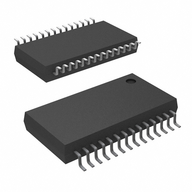
| Package / Case | 28-SSOP | 28-SSOP, 28-SOIC |
| Package / Case | - | 0.295 " |
| Package / Case | - | 7.5 mm |
| Protocol | RS232 | RS232 |
| Receiver Hysteresis | 500 mV | 500 mV |
| Supplier Device Package | 28-SSOP | 28-SSOP, 28-SOIC |
| Type | Transceiver | Transceiver |
| Voltage - Supply [Max] | 5.5 V | 5.5 V |
| Voltage - Supply [Min] | 4.5 V | 4.5 V |
Pricing
Prices provided here are for design reference only. For realtime values and availability, please visit the distributors directly
MAX211 Series
5-V multichannel 120kbps RS-232 line driver/receiver with +/-9V output & +/-15-kV ESD protection
| Part | Duplex | Package / Case | Package / Case | Mounting Type | Type | Protocol | Data Rate | Voltage - Supply [Max] | Voltage - Supply [Min] | Receiver Hysteresis | Operating Temperature [Min] | Operating Temperature [Max] | Supplier Device Package | Number of Drivers/Receivers | Package / Case | Package / Case |
|---|---|---|---|---|---|---|---|---|---|---|---|---|---|---|---|---|
Full | 0.209 in, 5.3 mm | 28-SSOP | Surface Mount | Transceiver | RS232 | 120 Kbps | 5.5 V | 4.5 V | 500 mV | -40 °C | 85 °C | 28-SSOP | 4, 5 | |||
Texas Instruments MAX211IDWThe MAX211 device consists of four line drivers, five line receivers, and a dual charge-pump circuit with ±15kV ESD protection pin to pin (serial-port connection pins, including GND). The device meets the requirements of TIA/EIA-232-F and provides the electrical interface between an asynchronous communication controller and the serial-port connector. The charge pump and four small external capacitors allow operation from a single 5V supply. The devices operate at data signaling rates up to 120kbit/s and a maximum of 30V/µs driver output slew rate.
The MAX211 has both shutdown (SHDN) and enable control (EN). In shutdown mode, the charge pumps are turned off, V+ is pulled down to VCC, V− is pulled to GND, and the transmitter outputs are disabled. This reduces supply current typically to 1µA. EN is used to put the receiver outputs into the high-impedance state to allow wired-OR connection of two RS-232 ports. It has no effect on the RS-232 drivers or the charge pumps.
The MAX211 device consists of four line drivers, five line receivers, and a dual charge-pump circuit with ±15kV ESD protection pin to pin (serial-port connection pins, including GND). The device meets the requirements of TIA/EIA-232-F and provides the electrical interface between an asynchronous communication controller and the serial-port connector. The charge pump and four small external capacitors allow operation from a single 5V supply. The devices operate at data signaling rates up to 120kbit/s and a maximum of 30V/µs driver output slew rate.
The MAX211 has both shutdown (SHDN) and enable control (EN). In shutdown mode, the charge pumps are turned off, V+ is pulled down to VCC, V− is pulled to GND, and the transmitter outputs are disabled. This reduces supply current typically to 1µA. EN is used to put the receiver outputs into the high-impedance state to allow wired-OR connection of two RS-232 ports. It has no effect on the RS-232 drivers or the charge pumps. | Full | 28-SOIC | Surface Mount | Transceiver | RS232 | 120 Kbps | 5.5 V | 4.5 V | 500 mV | -40 °C | 85 °C | 28-SOIC | 4, 5 | 0.295 " | 7.5 mm | |
Full | 0.209 in, 5.3 mm | 28-SSOP | Surface Mount | Transceiver | RS232 | 120 Kbps | 5.5 V | 4.5 V | 500 mV | -40 °C | 85 °C | 28-SSOP | 4, 5 | |||
Full | 28-SOIC | Surface Mount | Transceiver | RS232 | 120 Kbps | 5.5 V | 4.5 V | 500 mV | 0 °C | 70 ░C | 28-SOIC | 4, 5 | 0.295 " | 7.5 mm | ||
Texas Instruments MAX211CDWRThe MAX211 device consists of four line drivers, five line receivers, and a dual charge-pump circuit with ±15kV ESD protection pin to pin (serial-port connection pins, including GND). The device meets the requirements of TIA/EIA-232-F and provides the electrical interface between an asynchronous communication controller and the serial-port connector. The charge pump and four small external capacitors allow operation from a single 5V supply. The devices operate at data signaling rates up to 120kbit/s and a maximum of 30V/µs driver output slew rate.
The MAX211 has both shutdown (SHDN) and enable control (EN). In shutdown mode, the charge pumps are turned off, V+ is pulled down to VCC, V− is pulled to GND, and the transmitter outputs are disabled. This reduces supply current typically to 1µA. EN is used to put the receiver outputs into the high-impedance state to allow wired-OR connection of two RS-232 ports. It has no effect on the RS-232 drivers or the charge pumps.
The MAX211 device consists of four line drivers, five line receivers, and a dual charge-pump circuit with ±15kV ESD protection pin to pin (serial-port connection pins, including GND). The device meets the requirements of TIA/EIA-232-F and provides the electrical interface between an asynchronous communication controller and the serial-port connector. The charge pump and four small external capacitors allow operation from a single 5V supply. The devices operate at data signaling rates up to 120kbit/s and a maximum of 30V/µs driver output slew rate.
The MAX211 has both shutdown (SHDN) and enable control (EN). In shutdown mode, the charge pumps are turned off, V+ is pulled down to VCC, V− is pulled to GND, and the transmitter outputs are disabled. This reduces supply current typically to 1µA. EN is used to put the receiver outputs into the high-impedance state to allow wired-OR connection of two RS-232 ports. It has no effect on the RS-232 drivers or the charge pumps. | Full | 28-SOIC | Surface Mount | Transceiver | RS232 | 120 Kbps | 5.5 V | 4.5 V | 500 mV | 0 °C | 70 ░C | 28-SOIC | 4, 5 | 0.295 " | 7.5 mm | |
Texas Instruments MAX211CDBRThe MAX211 device consists of four line drivers, five line receivers, and a dual charge-pump circuit with ±15kV ESD protection pin to pin (serial-port connection pins, including GND). The device meets the requirements of TIA/EIA-232-F and provides the electrical interface between an asynchronous communication controller and the serial-port connector. The charge pump and four small external capacitors allow operation from a single 5V supply. The devices operate at data signaling rates up to 120kbit/s and a maximum of 30V/µs driver output slew rate.
The MAX211 has both shutdown (SHDN) and enable control (EN). In shutdown mode, the charge pumps are turned off, V+ is pulled down to VCC, V− is pulled to GND, and the transmitter outputs are disabled. This reduces supply current typically to 1µA. EN is used to put the receiver outputs into the high-impedance state to allow wired-OR connection of two RS-232 ports. It has no effect on the RS-232 drivers or the charge pumps.
The MAX211 device consists of four line drivers, five line receivers, and a dual charge-pump circuit with ±15kV ESD protection pin to pin (serial-port connection pins, including GND). The device meets the requirements of TIA/EIA-232-F and provides the electrical interface between an asynchronous communication controller and the serial-port connector. The charge pump and four small external capacitors allow operation from a single 5V supply. The devices operate at data signaling rates up to 120kbit/s and a maximum of 30V/µs driver output slew rate.
The MAX211 has both shutdown (SHDN) and enable control (EN). In shutdown mode, the charge pumps are turned off, V+ is pulled down to VCC, V− is pulled to GND, and the transmitter outputs are disabled. This reduces supply current typically to 1µA. EN is used to put the receiver outputs into the high-impedance state to allow wired-OR connection of two RS-232 ports. It has no effect on the RS-232 drivers or the charge pumps. | Full | 0.209 in, 5.3 mm | 28-SSOP | Surface Mount | Transceiver | RS232 | 120 Kbps | 5.5 V | 4.5 V | 500 mV | 0 °C | 70 ░C | 28-SSOP | 4, 5 | ||
Texas Instruments MAX211IDBRThe MAX211 device consists of four line drivers, five line receivers, and a dual charge-pump circuit with ±15kV ESD protection pin to pin (serial-port connection pins, including GND). The device meets the requirements of TIA/EIA-232-F and provides the electrical interface between an asynchronous communication controller and the serial-port connector. The charge pump and four small external capacitors allow operation from a single 5V supply. The devices operate at data signaling rates up to 120kbit/s and a maximum of 30V/µs driver output slew rate.
The MAX211 has both shutdown (SHDN) and enable control (EN). In shutdown mode, the charge pumps are turned off, V+ is pulled down to VCC, V− is pulled to GND, and the transmitter outputs are disabled. This reduces supply current typically to 1µA. EN is used to put the receiver outputs into the high-impedance state to allow wired-OR connection of two RS-232 ports. It has no effect on the RS-232 drivers or the charge pumps.
The MAX211 device consists of four line drivers, five line receivers, and a dual charge-pump circuit with ±15kV ESD protection pin to pin (serial-port connection pins, including GND). The device meets the requirements of TIA/EIA-232-F and provides the electrical interface between an asynchronous communication controller and the serial-port connector. The charge pump and four small external capacitors allow operation from a single 5V supply. The devices operate at data signaling rates up to 120kbit/s and a maximum of 30V/µs driver output slew rate.
The MAX211 has both shutdown (SHDN) and enable control (EN). In shutdown mode, the charge pumps are turned off, V+ is pulled down to VCC, V− is pulled to GND, and the transmitter outputs are disabled. This reduces supply current typically to 1µA. EN is used to put the receiver outputs into the high-impedance state to allow wired-OR connection of two RS-232 ports. It has no effect on the RS-232 drivers or the charge pumps. | Full | 0.209 in, 5.3 mm | 28-SSOP | Surface Mount | Transceiver | RS232 | 120 Kbps | 5.5 V | 4.5 V | 500 mV | -40 °C | 85 °C | 28-SSOP | 4, 5 | ||
Texas Instruments MAX211IDWRThe MAX211 device consists of four line drivers, five line receivers, and a dual charge-pump circuit with ±15kV ESD protection pin to pin (serial-port connection pins, including GND). The device meets the requirements of TIA/EIA-232-F and provides the electrical interface between an asynchronous communication controller and the serial-port connector. The charge pump and four small external capacitors allow operation from a single 5V supply. The devices operate at data signaling rates up to 120kbit/s and a maximum of 30V/µs driver output slew rate.
The MAX211 has both shutdown (SHDN) and enable control (EN). In shutdown mode, the charge pumps are turned off, V+ is pulled down to VCC, V− is pulled to GND, and the transmitter outputs are disabled. This reduces supply current typically to 1µA. EN is used to put the receiver outputs into the high-impedance state to allow wired-OR connection of two RS-232 ports. It has no effect on the RS-232 drivers or the charge pumps.
The MAX211 device consists of four line drivers, five line receivers, and a dual charge-pump circuit with ±15kV ESD protection pin to pin (serial-port connection pins, including GND). The device meets the requirements of TIA/EIA-232-F and provides the electrical interface between an asynchronous communication controller and the serial-port connector. The charge pump and four small external capacitors allow operation from a single 5V supply. The devices operate at data signaling rates up to 120kbit/s and a maximum of 30V/µs driver output slew rate.
The MAX211 has both shutdown (SHDN) and enable control (EN). In shutdown mode, the charge pumps are turned off, V+ is pulled down to VCC, V− is pulled to GND, and the transmitter outputs are disabled. This reduces supply current typically to 1µA. EN is used to put the receiver outputs into the high-impedance state to allow wired-OR connection of two RS-232 ports. It has no effect on the RS-232 drivers or the charge pumps. | Full | 28-SOIC | Surface Mount | Transceiver | RS232 | 120 Kbps | 5.5 V | 4.5 V | 500 mV | -40 °C | 85 °C | 28-SOIC | 4, 5 | 0.295 " | 7.5 mm | |
Texas Instruments MAX211IDBThe MAX211 device consists of four line drivers, five line receivers, and a dual charge-pump circuit with ±15kV ESD protection pin to pin (serial-port connection pins, including GND). The device meets the requirements of TIA/EIA-232-F and provides the electrical interface between an asynchronous communication controller and the serial-port connector. The charge pump and four small external capacitors allow operation from a single 5V supply. The devices operate at data signaling rates up to 120kbit/s and a maximum of 30V/µs driver output slew rate.
The MAX211 has both shutdown (SHDN) and enable control (EN). In shutdown mode, the charge pumps are turned off, V+ is pulled down to VCC, V− is pulled to GND, and the transmitter outputs are disabled. This reduces supply current typically to 1µA. EN is used to put the receiver outputs into the high-impedance state to allow wired-OR connection of two RS-232 ports. It has no effect on the RS-232 drivers or the charge pumps.
The MAX211 device consists of four line drivers, five line receivers, and a dual charge-pump circuit with ±15kV ESD protection pin to pin (serial-port connection pins, including GND). The device meets the requirements of TIA/EIA-232-F and provides the electrical interface between an asynchronous communication controller and the serial-port connector. The charge pump and four small external capacitors allow operation from a single 5V supply. The devices operate at data signaling rates up to 120kbit/s and a maximum of 30V/µs driver output slew rate.
The MAX211 has both shutdown (SHDN) and enable control (EN). In shutdown mode, the charge pumps are turned off, V+ is pulled down to VCC, V− is pulled to GND, and the transmitter outputs are disabled. This reduces supply current typically to 1µA. EN is used to put the receiver outputs into the high-impedance state to allow wired-OR connection of two RS-232 ports. It has no effect on the RS-232 drivers or the charge pumps. | Full | 0.209 in, 5.3 mm | 28-SSOP | Surface Mount | Transceiver | RS232 | 120 Kbps | 5.5 V | 4.5 V | 500 mV | -40 °C | 85 °C | 28-SSOP | 4, 5 |
Description
General part information
MAX211 Series
The MAX211 device consists of four line drivers, five line receivers, and a dual charge-pump circuit with ±15kV ESD protection pin to pin (serial-port connection pins, including GND). The device meets the requirements of TIA/EIA-232-F and provides the electrical interface between an asynchronous communication controller and the serial-port connector. The charge pump and four small external capacitors allow operation from a single 5V supply. The devices operate at data signaling rates up to 120kbit/s and a maximum of 30V/µs driver output slew rate.
The MAX211 has both shutdown (SHDN) and enable control (EN). In shutdown mode, the charge pumps are turned off, V+ is pulled down to VCC, V− is pulled to GND, and the transmitter outputs are disabled. This reduces supply current typically to 1µA. EN is used to put the receiver outputs into the high-impedance state to allow wired-OR connection of two RS-232 ports. It has no effect on the RS-232 drivers or the charge pumps.
The MAX211 device consists of four line drivers, five line receivers, and a dual charge-pump circuit with ±15kV ESD protection pin to pin (serial-port connection pins, including GND). The device meets the requirements of TIA/EIA-232-F and provides the electrical interface between an asynchronous communication controller and the serial-port connector. The charge pump and four small external capacitors allow operation from a single 5V supply. The devices operate at data signaling rates up to 120kbit/s and a maximum of 30V/µs driver output slew rate.