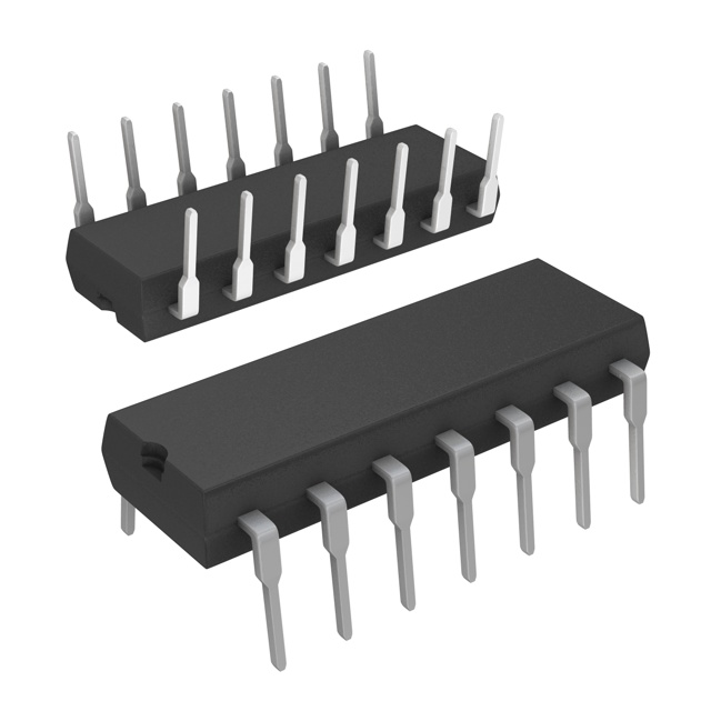
L6386E
ObsoleteIC GATE DRVR HALF-BRIDGE 14DIP
Deep-Dive with AI
Search across all available documentation for this part.

L6386E
ObsoleteIC GATE DRVR HALF-BRIDGE 14DIP
Deep-Dive with AI
Technical Specifications
Parameters and characteristics for this part
| Specification | L6386E |
|---|---|
| Channel Type | Independent |
| Current - Peak Output (Source, Sink) [custom] | 400 mA |
| Current - Peak Output (Source, Sink) [custom] | 650 mA |
| Driven Configuration | Half-Bridge |
| Gate Type | N-Channel MOSFET, IGBT |
| High Side Voltage - Max (Bootstrap) [Max] | 600 V |
| Input Type | Inverting |
| Logic Voltage - VIL, VIH | 1.5 V, 3.6 V |
| Mounting Type | Through Hole |
| Number of Drivers | 2 |
| Operating Temperature [Max] | 150 °C |
| Operating Temperature [Min] | -40 °C |
| Package / Case | 14-DIP |
| Package / Case [x] | 0.3 " |
| Package / Case [y] | 7.62 mm |
| Rise / Fall Time (Typ) [custom] | 30 ns |
| Rise / Fall Time (Typ) [custom] | 50 ns |
| Supplier Device Package | 14-DIP |
| Voltage - Supply [Max] | 17 V |
Pricing
Prices provided here are for design reference only. For realtime values and availability, please visit the distributors directly
| Distributor | Package | Quantity | $ | |
|---|---|---|---|---|
Description
General part information
L6386AD Series
The L6386AD is a high voltage gate driver, manufactured with the BCD™ "offline" technology, and able to drive simultaneously one high and one low-side power MOSFET or IGBT device. The high-side (floating) section is able to work with voltage rail up to 600 V. Both device outputs can independently sink and source 650 mA and 400 mA respectively and can be simultaneously driven high in order to drive asymmetrical half-bridge configurations.
The L6386AD device provides two input pins, two output pins and an enable pin (SD), and guarantees the outputs switch in phase with inputs. The logic inputs are CMOS/TTL compatible to ease the interfacing with controlling devices.
The L6386AD integrates a comparator (inverting input internally referenced to 0.5 V) that can be used to protect the device against fault events, like overcurrent. The DIAG output is a diagnostic pin, driven by the comparator, and used to signal a fault event occurrence to the controlling device.
Documents
Technical documentation and resources


