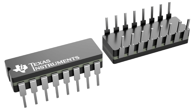
CD54HC191F3A
ActiveHIGH SPEED CMOS LOGIC PRESETTABLE SYNCHRONOUS 4-BIT BINARY UP/DOWN COUNTER
Deep-Dive with AI
Search across all available documentation for this part.

CD54HC191F3A
ActiveHIGH SPEED CMOS LOGIC PRESETTABLE SYNCHRONOUS 4-BIT BINARY UP/DOWN COUNTER
Deep-Dive with AI
Technical Specifications
Parameters and characteristics commom to parts in this series
| Specification | CD54HC191F3A | 54HC191 Series |
|---|---|---|
| Count Rate | 35 MHz | 35 MHz |
| Direction | Down, Up | Down, Up |
| Logic Type | Binary Counter | Binary Counter |
| Mounting Type | Through Hole | Surface Mount, Through Hole |
| Number of Bits per Element | 4 | 4 |
| Number of Elements [custom] | 1 | 1 |
| Operating Temperature | - | 25 °C |
| Operating Temperature [Max] | 125 °C | 125 °C |
| Operating Temperature [Min] | -55 C | -55 C |
| Package / Case | 16-CDIP (0.300", 7.62mm) | Die, 16-CDIP (0.300", 7.62mm) |
| Reset | Asynchronous | Asynchronous |
| Supplier Device Package | 16-CDIP | Die, 16-CDIP |
| Timing | Synchronous | Synchronous |
| Trigger Type | Positive Edge | Positive Edge |
| Voltage - Supply [Max] | 6 V | 6 V |
| Voltage - Supply [Min] | 2 V | 2 V |
Pricing
Prices provided here are for design reference only. For realtime values and availability, please visit the distributors directly
54HC191 Series
IC BINARY COUNTER 4-BIT DIE
| Part | Logic Type | Supplier Device Package | Timing | Package / Case | Reset | Number of Bits per Element | Number of Elements [custom] | Mounting Type | Trigger Type | Direction | Operating Temperature | Count Rate | Voltage - Supply [Max] | Voltage - Supply [Min] | Operating Temperature [Min] | Operating Temperature [Max] |
|---|---|---|---|---|---|---|---|---|---|---|---|---|---|---|---|---|
Binary Counter | Die | Synchronous | Die | Asynchronous | 4 | 1 | Surface Mount | Positive Edge | Down, Up | 25 °C | ||||||
Texas Instruments CD54HC191F3AThe CD54/74HC190 are asynchronously presettable BCD decade counters, whereas the CD54/74HC191 and CD54/74HCT191 are asynchronously presettable binary counters.
Presetting the counter to the number on preset data inputs (A–D) is accomplished by a low asynchronous parallel load (LOAD)\ input. Counting occurs when LOAD\ is high, count enable (CTEN)\ is low, and the down/up (D/U) input is either high for down counting or low for up counting. The counter is decremented or incremented synchronously with the low-to-high transition of the clock.
When an overflow or underflow of the counter occurs, the MAX/MIN output, which is low during counting, goes high and remains high for one clock cycle. This output can be used for look-ahead carry in high-speed cascading (see Figure 1). The MAX/MIN output also initiates the ripple clock (RCO)\ output, which is normally high, goes low and remains low for the low-level portion of the clock pulse. These counters can be cascaded using RCO\ (see Figure 2).
If a decade counter is preset to an illegal state or assumes an illegal state when power is applied, it returns to the normal sequence in one or two counts, as shown in the state diagrams (see Figure 3).
The CD54/74HC190 are asynchronously presettable BCD decade counters, whereas the CD54/74HC191 and CD54/74HCT191 are asynchronously presettable binary counters.
Presetting the counter to the number on preset data inputs (A–D) is accomplished by a low asynchronous parallel load (LOAD)\ input. Counting occurs when LOAD\ is high, count enable (CTEN)\ is low, and the down/up (D/U) input is either high for down counting or low for up counting. The counter is decremented or incremented synchronously with the low-to-high transition of the clock.
When an overflow or underflow of the counter occurs, the MAX/MIN output, which is low during counting, goes high and remains high for one clock cycle. This output can be used for look-ahead carry in high-speed cascading (see Figure 1). The MAX/MIN output also initiates the ripple clock (RCO)\ output, which is normally high, goes low and remains low for the low-level portion of the clock pulse. These counters can be cascaded using RCO\ (see Figure 2).
If a decade counter is preset to an illegal state or assumes an illegal state when power is applied, it returns to the normal sequence in one or two counts, as shown in the state diagrams (see Figure 3). | Binary Counter | 16-CDIP | Synchronous | 16-CDIP (0.300", 7.62mm) | Asynchronous | 4 | 1 | Through Hole | Positive Edge | Down, Up | 35 MHz | 6 V | 2 V | -55 C | 125 °C | |
Binary Counter | Die | Synchronous | Die | Asynchronous | 4 | 1 | Surface Mount | Positive Edge | Down, Up | 25 °C |
Description
General part information
54HC191 Series
The CD54/74HC190 are asynchronously presettable BCD decade counters, whereas the CD54/74HC191 and CD54/74HCT191 are asynchronously presettable binary counters.
Presetting the counter to the number on preset data inputs (A–D) is accomplished by a low asynchronous parallel load (LOAD)\ input. Counting occurs when LOAD\ is high, count enable (CTEN)\ is low, and the down/up (D/U) input is either high for down counting or low for up counting. The counter is decremented or incremented synchronously with the low-to-high transition of the clock.
When an overflow or underflow of the counter occurs, the MAX/MIN output, which is low during counting, goes high and remains high for one clock cycle. This output can be used for look-ahead carry in high-speed cascading (see Figure 1). The MAX/MIN output also initiates the ripple clock (RCO)\ output, which is normally high, goes low and remains low for the low-level portion of the clock pulse. These counters can be cascaded using RCO\ (see Figure 2).
Documents
Technical documentation and resources


