


BD933N5EFJ-CE2
ActiveNANO CAP™, QUICUR™, 500MA 3.3V, FIXED OUTPUT LDO REGULATOR FOR AUTOMOTIVE

BD933N5EFJ-CE2
ActiveNANO CAP™, QUICUR™, 500MA 3.3V, FIXED OUTPUT LDO REGULATOR FOR AUTOMOTIVE
Description
General part information
BD933N5EFJ-C Series
BD933N5EFJ-C is linear regulators using the Nano Cap™ topology designed as low current consumption products for power supplies in various automotive applications requiring a direct connection to the battery. This product is designed for up to 45V as an absolute maximum voltage and to operate until 500mA for theoutput current with low current consumption 25μA (Typ). This can regulate the output with a very high accuracy ±2.0%.What is Nano Cap™?Nano Cap™ is a combination of technologies which allow stable operation even if output capacitance is connected with the range of nF unit.What is QuiCur™?QuiCur™ is a combination of technologies that provides high-speed load response.
Technical Specifications
Parameters and characteristics for this part
| Specification | BD933N5EFJ-CE2 |
|---|---|
| Control Features | Enable |
| Current - Output | 500 mA |
| Current - Quiescent (Iq) | 50 µA |
| Grade | Automotive |
| Mounting Type | Surface Mount |
| Number of Regulators | 1 |
| Operating Temperature (Max) | 150 °C |
| Operating Temperature (Min) | -40 °C |
| Output Configuration | Positive |
| Output Type | Fixed |
| Package Features | Exposed Pad |
| Package Length | 0.154 in |
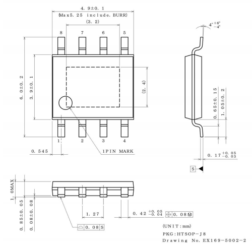
| Package Name | 8-SOIC, 8-HTSOP-J |
| Package Width | 3.9 mm |
| Protection Features | Under Voltage Lockout (UVLO), Over Temperature, Over Current, Short Circuit |
| Qualification | AEC-Q100 |
| Voltage - Input (Max) | 42 V |
| Voltage - Output (Min/Fixed) | 3.3 V |
| Voltage Dropout (Max) | 1.25 V |
Pricing
Prices provided here are for design reference only. For realtime values and availability, please visit the distributors directly
Sign in to see pricing
Create a free account to access distributor pricing data.
CAD
3D models and CAD resources for this part
Documents
Technical documentation and resources