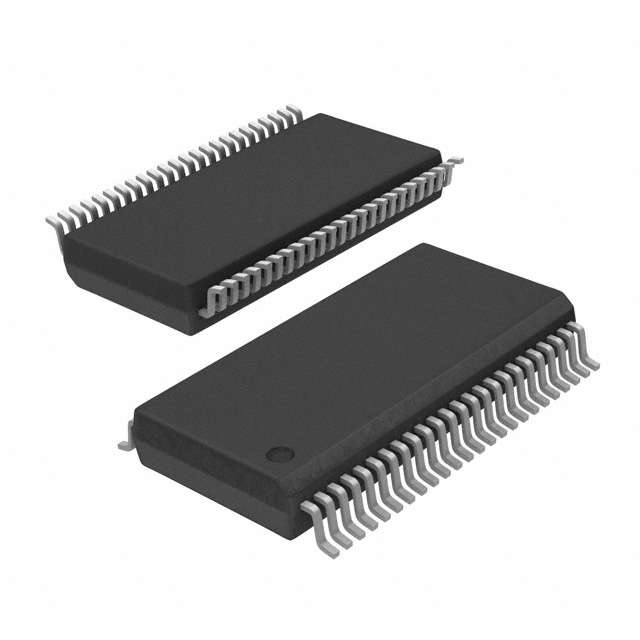
LTC1853CFW#PBF
Active8-CHANNEL, 10-BIT/12-BIT, 400KSPS, LOW POWER, SAMPLING ADCS
Deep-Dive with AI
Search across all available documentation for this part.

LTC1853CFW#PBF
Active8-CHANNEL, 10-BIT/12-BIT, 400KSPS, LOW POWER, SAMPLING ADCS
Deep-Dive with AI
Technical Specifications
Parameters and characteristics for this part
| Specification | LTC1853CFW#PBF |
|---|---|
| Architecture | SAR |
| Configuration | MUX-S/H-ADC |
| Data Interface | Parallel |
| Features | PGA, Selectable Address |
| Input Type | Single Ended, Differential |
| Mounting Type | Surface Mount |
| Number of A/D Converters | 1 |
| Number of Bits | 12 bits |
| Number of Inputs | 8 |
| Operating Temperature [Max] | 70 °C |
| Operating Temperature [Min] | 0 °C |
| Package / Case | 48-TFSOP |
| Package / Case | 0.24 in |
| Package / Case [custom] | 6.1 mm |
| Ratio - S/H:ADC | 1:1 |
| Reference Type | External, Internal |
| Supplier Device Package | 48-TSSOP |
| Voltage - Supply, Analog [Max] | 5.5 V |
| Voltage - Supply, Analog [Min] | 2.7 V |
| Voltage - Supply, Digital [Max] | 5.5 V |
| Voltage - Supply, Digital [Min] | 2.7 V |
Pricing
Prices provided here are for design reference only. For realtime values and availability, please visit the distributors directly
| Distributor | Package | Quantity | $ | |
|---|---|---|---|---|
| Digikey | Tube | 1 | $ 19.90 | |
| 10 | $ 14.46 | |||
| 25 | $ 13.06 | |||
| 100 | $ 11.50 | |||
| 250 | $ 10.75 | |||
| 500 | $ 10.40 | |||
Description
General part information
LTC1853 Series
The 10-bit LTC1852 and 12-bit LTC1853 are complete 8-channel data acquisition systems. They include a flexible 8-channel multiplexer, a 400ksps successive approximation analog-to-digital converter, an internal reference and a parallel output interface. The multiplexer can be configured for single-ended or differential inputs, two gain ranges and unipolar or bipolar operation. The ADCs have a scan mode that will repeatedly cycle through all 8 multiplexer channels and can also be programmed to sequence through up to 16 addresses and configurations. The sequence can also be read back from internal memory.The reference and buffer amplifier provide pin strappable ranges of 4.096V, 2.5V and 2.048V. The parallel output includes the 10-bit or 12-bit conversion result plus the 4-bit multiplexer address. The digital outputs are powered from a separate supply allowing for easy interface to 3V digital logic. Typical power consumption is 10mW at 400ksps from a single 5V supply and 3mW at 250ksps from a single 3V supply.ApplicationsHigh Speed Data AcquisitionTest and MeasurementImaging SystemsTelecommunicationsIndustrial Process ControlSpectrum Analysis
Documents
Technical documentation and resources


